


3-41
Cisco ASR 903 Router Hardware Installation Guide
OL-25178-05
Chapter 3 Installing the Cisco ASR 903 Router
Connecting the Cisco ASR 903 Router to the Network
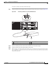
Connecting Cables to a GPS Interface
The following sections describe how to connect cables from the Cisco ASR 903 Router to a GPS unit for
input or output timing of frequency:
• Connecting Cables to the Input 10Mhz or 1PPS Interface, page 3-41
• Connecting Cables to the Output 10Mhz or 1PPS Interface, page 3-41
• Connecting Cables to the ToD Interface, page 3-41
Note A Y-cable is required to connect to a primary and backup RSP in order to ensure that the router continues
to transmit timing signals in the event of a network failure. For a mini-coax connection, this Y-cable can
be part number CAB-BNC-7INY (7 inch BNC Y-cable). For an Ethernet connection, this Y-cable can be
a RJ45 Cat5 1-to-2 splitter (3 female port RJ45 connector).
Note When installing the cabling to the RSPs, we recommend that you leave a service loop of extra cabling
sufficient to allow for fan tray removal.
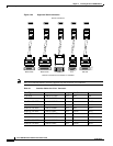
Connecting Cables to the Input 10Mhz or 1PPS Interface
Step 1 Connect one end of a mini-coax Y-cable to the GPS unit.
Step 2 Connect one end of the split-side Y-cable mini-coax to the 10Mhz or 1PPS port on the primary RSP of
the Cisco ASR 903 Router.
Step 3 Connect the other end of the split-side Y-cable mini-coax to the 10Mhz or 1PPS port on the backup RSP
of the Cisco ASR 903 Router.
Connecting Cables to the Output 10Mhz or 1PPS Interface
Step 1 Connect one end of a mini-coax Y-cable to the Slave unit.
Step 2 Connect one end of the split-side Y-cable mini-coax to the 10Mhz or 1PPS port on the primary RSP of
the Cisco ASR 903 Router.
Step 3 Connect the other end of the split-side Y-cable mini-coax to the 10Mhz or 1PPS port on the backup RSP
of the Cisco ASR 903 Router.
Connecting Cables to the ToD Interface
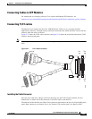
Step 1 Connect one end of a straight-through Ethernet cable to the GPS unit.
Step 2 Connect one end of the split-side Y-cable Ethernet to the ToD port on the primary RSP of the
CiscoASR903Router.
Step 3 Connect the other end of the split-side Y-cable Ethernet to the ToD port on the backup RSP of the
CiscoASR903Router.
Note For instructions on how to configure clocking, see the Cisco ASR 903 Router Software Configuration
Guide.