


3-30
Cisco ASR 903 Router Hardware Installation Guide
OL-25178-05
Chapter 3 Installing the Cisco ASR 903 Router
Connecting the Cisco ASR 903 Router to the Network
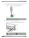
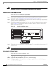
Step 5 If the power supply bay is to remain empty, install a blank filler plate (Cisco part number
A900-PWR-BLANK) over the opening, and secure it with the captive installation screws.
Connecting the Cisco ASR 903 Router to the Network
The following sections describe how to connect cables on the Cisco ASR 903 Router:
• Connecting Console Cables, page 3-30
• Connecting to the Auxiliary Port, page 3-36
• Connecting a Management Ethernet Cable, page 3-38
• Installing and Removing SFP and XFP Modules, page 3-38
• Connecting a USB Flash Device, page 3-38
• Connecting Timing Cables, page 3-39
• Connecting Ethernet Cables, page 3-42
• Connecting Cables to SFP Modules, page 3-43
• Connecting T1/E1 cables, page 3-43
• Connecting Serial Cables, page 3-45
• Connecting the Fan Tray Alarm Port, page 3-47
• Connector and Cable Specifications, page 3-47
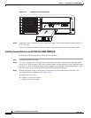
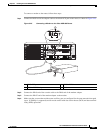
Note When installing the cabling to the RSPs, we recommend that you leave a service loop of extra cabling
sufficient to allow for fan tray removal.
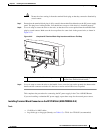
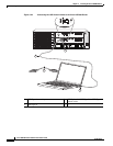
Connecting Console Cables
The following sections describe how to connect to the Cisco ASR 903 Router using console cables:
• Connecting to the Serial Port using Microsoft Windows, page 3-31
• Connecting to the Console Port using Mac OS X, page 3-33
• Connecting to the Console Port using Linux, page 3-33
• Installing the Cisco Microsoft Windows USB Device Driver, page 3-34
• Uninstalling the Cisco Microsoft Windows USB Driver, page 3-35
Note You cannot use the USB and RS232 console ports at the same time; if you insert the USB cable into the
router, the RS232 port is disabled.