


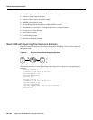

SRB Configuration Examples
BC-152
Bridging and IBM Networking Configuration Guide
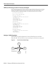
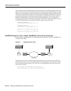
Configuration of Router A
source-bridge ring-group 100
!
interface Serial1
encapsulation frame-relay
!
interface Serial1.1 point-to-point
frame-relay interface-dlci 30 ietf
source-bridge 200 1 100 conserve-ring
source-bridge spanning
!
interface Serial1.2 point-to-point
frame-relay interface-dlci 31 ietf
source-bridge 300 1 100 conserve-ring
source-bridge spanning
!
interface TokenRing0
source-bridge 500 1 100
Configuration on Router B
source-bridge ring-group 200
!
interface Serial0
encapsulation frame-relay
!
interface Serial0.30 point-to-point
frame-relay interface-dlci 30 ietf
source-bridge 100 1 200 conserve-ring
source-bridge spanning
!
interface TokenRing0
source-bridge 600 1 200
Configuration on Router C
source-bridge ring-group 300
!
interface Serial0
encapsulation frame-relay
!
interface Serial0.31 point-to-point
frame-relay interface-dlci 31 ietf
source-bridge 100 1 300 conserve-ring
source-bridge spanning
!
interface TokenRing0
source-bridge 900 1 300
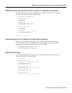
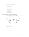
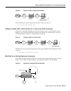
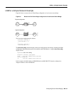
Adding a Static RIF Cache Entry Example
In the example configuration in Figure 60, the path between rings 8 and 9 connected via Bridge 1 is
described by the route descriptor 0081.0090. A full RIF, including the route control field, would be
0630.0081.0090.