


SRB Configuration Examples
BC-156
Bridging and IBM Networking Configuration Guide
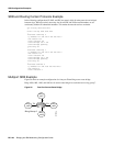
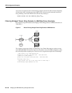
The command for the Token Ring interface specifies that the access list 701 be applied on the source
address of frames going out to the Token Ring, and the command for the Ethernet interface specifies
that this access list be applied on the source address frames entering the interface from Ethernet. This
would work if both interfaces used the same bit ordering, but Token Rings and Ethernets use opposite
(swapped) bit orderings in their addresses in relationship to each other. Therefore, the address of
Host E on the Token Ring is not 0110.2222.3333, but rather 8008.4444.cccc, resulting in the
following configuration. The following configuration is better. This example shows that access lists
for Token Ring and Ethernet should be kept completely separate from each other.
interface tokenring 0
source-bridge input-address-list 702
!
interface ethernet 0
bridge-group 1 input-address-list 701
!
access-list 701 permit 0110.2222.3333
!!
access-list 702 permit 0110.1234.5678
NetBIOS Support with a Static NetBIOS Cache Entry Example
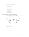
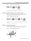
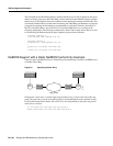
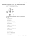
Figure 64 shows a NetBIOS client on a Token Ring connected through a cloud to a NetBIOS server
on another Token Ring.
Figure 64 Specifying a Static Entry
In Figure 64, a static entry is created in the router attached to ring 1 on the client side of the ring
group. The static entry is to the server DEF, which is reached through the router attached to ring 3.
If server DEF has the MAC address 0110.2222.3333, the configuration for the static entry on the
client side is as follows:
rif 0110.2222.3333 0630.0021.0030 ring-group 2
netbios name-cache 0110.2222.3333 DEF ring-group 2
Token
Ring 1
Client ABC
Ring group 2
Token
Ring 3
S1199a
Server DEF
0110.222.333
Bridge 1Bridge 1