


Configuring Data-Link Switching Plus
DLSw+ Configuration Examples
BC-332
Cisco IOS Bridging and IBM Networking Configuration Guide
78-11737-02
dlsw remote-peer 0 tcp 10.1.17.1
interface loopback 0
ip address 10.2.24.3 255.255.255.0
int e1
ip address 150.150.2.2 255.255.255.0
dlsw transparent redundancy-enable 9999.9999.9999 master priority 1
dlsw transparent timers sna 1500
Router C
dlsw local-peer peer-id 10.2.24.4
dlsw remote-peer 0 tcp 10.2.17.1
interface loopback 0
ip address 10.2.24.4 255.255.255.0
int e1
ip address 150.150.2.3 255.255.255.0
dlsw transparent redundancy-enable 9999.9999.9999
Router D
dlsw local-peer peer-id 10.2.17.1 promiscuous
DLSw+ with Ethernet Redundancy Enabled for Switch Support Configuration
Example
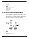
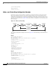
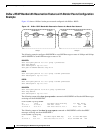
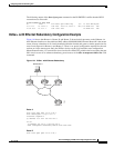
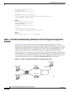
Figure 145 is a sample configuration of the DLSw+ Ethernet Redundancy feature in a switched
environment. The ethernet switch sees the device with MAC address 4000.0010.0001 one port at a time
because Router A and Router B have mapped different MAC addresses to it. This configuration is known
as MAC-address mapping. Router A is configured so that MAC address 4000.0001.0000 maps to the
actual device with MAC address 4000.0010.0001. Router B is configured so that MAC address
4000.0201.0001 maps to the actual device with MAC address 4000.0010.0001. Router A and B backup
one another. Router A is configured as the master with a default priority of 100. Master Router A waits
1.5 seconds after it receives the first IWANTIT primitive before assigning the new SNA circuit to one of
its ethernet redundancy peers because of the dlsw transparent timers sna 1500 command.
Figure 145 DLSw+ with Ethernet Redundancy in a Switched Environment
W
orkstation X
Ethernet switch
Workstation
Z
4000.0010.0001
W
orkstation Y
Router A
Router B
17956