


Adding or Replacing a DC PEM
10
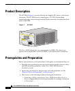
Cisco 10005 ESR DC Power Entry Module Installation
78-12653-01
Step 2 Set the power switch on the PEM that you are replacing to the 0 (Off) position. If
you have redundant PEMs, be sure to leave one PEM turned on.
Caution Do not power off both of the DC PEMs in a redundant system, or the system
shuts and down all data traffic stops. Only power off the DC PEM you are
replacing.
Step 3 Turn off power to the branch circuit that provides power to the PEM that you are
replacing.
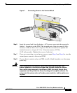
Step 4 At the terminal block on the PEM that you turned off, use a voltmeter to verify
that there is no power present.
Warning
Do not allow the test probes of the voltmeter to touch each other while they
are touching the power terminals. This is an ENERGY HAZARD to you, to the
voltmeter, and to the wires connecting the router to its power source.
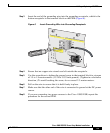
Step 5 Use a screwdriver to loosen the screws on the PEM terminal block and remove the
wires. Be sure to disconnect the ground (bottom wire) last.
Warning
When you are installing or replacing the unit, the ground connection must
always be made first and disconnected last.
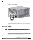
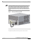
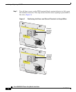
Step 6 Loosen the captive screws on the DC PEM you are removing and pull the PEM
from the chassis using the handle on the faceplate (Figure 3).
Step 7 Ensure that the power switch on the new DC PEM is set to 0 (Off).
Step 8 Insert the new DC PEM all the way into the power bay (see Figure 3) to ensure a
secure connection to the midplane. Tighten the captive screws that hold the PEM
in place.
If you do no not install a new PEM right away, install a blank faceplate over the
empty power bay.