


Adding or Replacing a DC PEM
18
Cisco 10005 ESR DC Power Entry Module Installation
78-12653-01
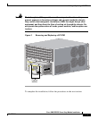
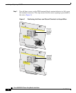
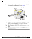
Step 9 Secure the power cabling to the chassis by feeding a tie wrap through the slot on
the side of the chassis and binding the cables. Dress the cables so that the fan
assembly on the right and the air filter on the left can be removed if necessary.
Checking the DC Power Connection
Follow these steps to verify that you have correctly connected DC power to the
Cisco 10005 chassis:
Step 1 Make sure the circuit breaker on the PEM you have just installed is still set to 0
(Off).
Step 2 Turn on power to the DC circuit.
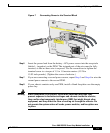
Step 3 Use a voltmeter to check the voltage at the terminal block on the PEM. Connect
the voltmeter’s positive contact to the positive (+) terminal on the terminal block.
Connect the voltmeter’s negative contact to the negative (–) terminal on the
terminal block. If the power is wired correctly:
• The voltmeter registers approximately +48VDC to +56VDC (or battery float
voltage).
• The yellow Fault LED on the PEM lights.
Warning
Do not allow the test probes of the voltmeter to touch each other while they
are touching the power terminals. This is an ENERGY HAZARD to you, to the
voltmeter, and to the wires connecting the router to its power source.
Step 4 Flip the circuit breakers on the PEMs to | (On). If the power is properly connected:
• The green Power LED lights on each PEM. The green LED indicates that the
PEM is making power available to the chassis in the proper voltage range.
• The yellow Fault LED on each PEM goes out.
• The fans start to turn. A slight delay in fan startup is normal.