


Adding or Replacing a DC PEM
16
Cisco 10005 ESR DC Power Entry Module Installation
78-12653-01
Connecting DC Power
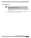
Warning
Only a DC power source that is isolated from AC mains with reinforced
insulation, and that complies with the other safety extra-low voltage (SELV)
requirements in UL1950, CSA 950 3rd Edition, EN 60950, and IEC950, can be
connected to a Cisco 10005 system. This requirement ensures that in a
catastrophic power source fault condition, hazardous voltages are not
present on power terminals and connectors.
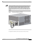
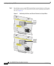
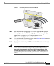
Follow these steps to connect DC power to the Cisco 10005 ESR. Refer to
Figure 7.
Step 1 Ensure that power in the DC circuit is off.
Step 2 Ensure that the PEMs are fully inserted into the chassis and secured with their
captive screws.
Step 3 Ensure that the circuit breaker on the newly installed PEM is set to 0 (Off).
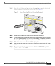
Step 4 Turn the + and – screws on the new PEM’s terminal block counter-clockwise to
fully open the terminal connectors. This step ensures that the correct opening is
presented for the wires (see Figure 5).
Step 5 Insert the battery return wire from the external power source into the receptacle
labeled + (positive) on the PEM (Figure 7). The stripped part of the wire must be
fully inserted so that no bare wire is exposed. Use the screwdriver to tighten the
terminal screw to a torque of 1.5 to 1.8 newton meters (13.28 to
15.93 inch-pounds). (Tighten the screws clockwise.)
Warning
The illustration shows the DC power supply terminal block. Wire the DC
power supply as illustrated. The proper wiring sequence is ground to
ground, positive to positive, and negative to negative. The ground wire must
always be connected first and disconnected last.