


17
Cisco 10005 ESR DC Power Entry Module Installation
78-12653-01
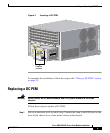
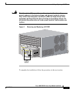
Adding or Replacing a DC PEM
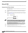
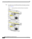
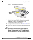
Figure 7 Connecting Power to the Terminal Block
Step 6 Insert the power lead from the battery –48V power source into the receptacle
labeled – (negative) on the PEM. The stripped part of the wire must be fully
inserted, so that no bare wire is exposed. Use the screwdriver to tighten the
terminal screw to a torque of 1.5 to 1.8 newton meters (13.28 to
15.93 inch-pounds). (Tighten the screws clockwise.)
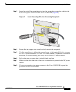
Step 7 If you are connecting a second power source, repeat Step 5 and Step 6 to wire the
second power source to the second PEM.
Step 8 If your chassis contains only one PEM, install a blank faceplate over the empty
power bay.
Warning
Blank faceplates (filler panels) serve three important functions: they
prevent exposure to hazardous voltages and currents inside the chassis;
they confine electromagnetic interference (EMI) that might disrupt other
equipment; and they direct the flow of cooling air through the chassis. Do
not operate the system unless all cards, power modules, and faceplates are
in place.
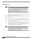
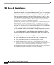
CAUTION: USE COPPER CONDUCTORS ONLY
ATTENTION: N'UTILISEZ QUE DES CONDUCTEURS EN CURVE
CAUTION: TERMINALS MAY BE ENERGIZED. TURN OFF POWER SOURCE CIRCUIT
BREAKER AND REMOVE POWERSUPPLY BEFORE ACCESSING TERMINALS.
G
M
L
POWER
FAULT
MIS-
WIRE
THIS UNIT HAS MORE THAN ONE POWER
SUPPLY CORD. DISCONNECT TWO (2)
POWER SUPPLY CORDS BEFORE
SERVICING TO AVOID ELECTRIC SHOCK.
CAUTION
CAUTION: USE COPPER CONDUCTORS ONLY
ATTENTION: N'UTILISEZ QUE DES CONDUCTEURS EN CURVE
CAUTION: TERMINALS MAY BE ENERGIZED. TURN OFF POWER SOURCE CIRCUIT
BREAKER AND REMOVE POWERSUPPLY BEFORE ACCESSING TERMINALS.
G
M
L
POWER
FAULT
MISWIRE
THIS UNIT HAS MORE THAN ONE POWER
SUPPLY CORD. DISCONNECT TWO (2)
POWER SUPPLY CORDS BEFORE
SERVICING TO AVOID ELECTRIC SHOCK.
CAUTION
53628
INPUT
-48/60 V
35A