


15
Cisco 10005 ESR DC Power Entry Module Installation
78-12653-01
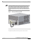
Adding or Replacing a DC PEM
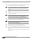
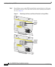
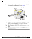
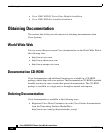
Step 3 Insert the end of the grounding wire into the grounding receptacle, which is the
bottom receptacle in the terminal block on the PEM (Figure 6).
Figure 6 Insert Grounding Wire into Grounding Receptacle
Step 4
Ensure that no copper wire strands are left outside the receptacle.
Step 5 Use the screwdriver to tighten the ground screw in the terminal block to a torque
of 1.5 to 1.8 newton meters (13.28 to 15.93 inch-pounds). (Tighten in a clockwise
direction.) To avoid breaking the screw, do no exceed 2.3 newton meters.
Step 6 Pull on the wire to ensure that it is held firmly in place.
Step 7 Make sure that the other end of the wire is connected to ground at the DC power
source.
Step 8 If you are connecting two power sources to the Cisco 10005 ESR, repeat this
procedure for the second PEM.
CAUTION: USE COPPER CONDUCTORS ONLY
ATTENTION: N'UTILISEZ QUE DES CONDUCTEURS EN CURVE
CAUTION: TERMINALS MAY BE ENERGIZED. TURN OFF POWER SOURCE CIRCUIT
BREAKER AND REMOVE POWERSUPPLY BEFORE ACCESSING TERMINALS.
G
M
L
POWER
FAULT
THIS UNIT HAS MORE THAN ONE POWER
SUPPLY CORD. DISCONNECT TWO (2)
POWER SUPPLY CORDS BEFORE
SERVICING TO AVOID ELECTRIC SHOCK.
CAUTION
CAUTION: USE COPPER CONDUCTORS ONLY
ATTENTION: N'UTILISEZ QUE DES CONDUCTEURS EN CURVE
CAUTION: TERMINALS MAY BE ENERGIZED. TURN OFF POWER SOURCE CIRCUIT
BREAKER AND REMOVE POWERSUPPLY BEFORE ACCESSING TERMINALS.
G
M
L
MISWIRE
THIS UNIT HAS MORE THAN ONE POWER
SUPPLY CORD. DISCONNECT TWO (2)
POWER SUPPLY CORDS BEFORE
SERVICING TO AVOID ELECTRIC SHOCK.
CAUTION
53627
INPUT
-48/60 V
35A