


17
Warning
This equipment must be grounded. Never defeat the ground conductor or operate the equipment in the absence of
a suitably installed ground conductor. Contact the appropriate electrical inspection authority or an electrician if
you are uncertain that suitable grounding is available.
Statement 1024
Warning
This unit might have more than one power supply connection. All connections must be removed to de-energize the
unit.
Statement 1028
Warning
This product relies on the building’s installation for short-circuit (overcurrent) protection. Ensure that the
protective device is rated not greater than: AC power supplies 20 A and DC power supplies 40 A.
Statement 1005
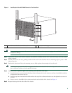
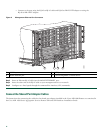
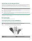
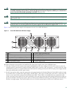
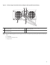
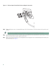
Figure 11 shows the DC power supply and components for the Cisco ASR 1006 Router.
Figure 11 Cisco ASR 1006 Router DC Power Supply
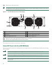
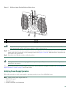
Read these important notices before you install the DC-input power supply in the Cisco ASR1006 router:
• The color coding of the DC-input power supply leads depends on the color coding of the DC power source at your site.
Typically, green or green/yellow is used for ground (GND), black is used for -48V on negative (–) terminal and red is used
for RTN on the positive (+) terminal. Make certain the lead color coding you choose for the DC-input power supply matches
lead color coding used at the DC power source.
• For DC input power cables, select the appropriate wire gauge based on the National Electrical Code (NEC) and local codes
for 40-amp service at nominal DC input voltage (–48/–60 VDC). Three pairs of cable leads, source DC (–) and source DC
return (+), are required for each power distribution unit (PDU). These cables are available from any commercial cable
vendor. All input power cables for the chassis should have the same wire gauge and cable lengths should match within 10
percent of deviation. Each DC input power cable is terminated at the PDU by a cable lug. The cable lugs must be dual-hole,
and have a straight tongue. They must be able to fit over 1/4-inch terminal studs at 0.625-inch (15.88-mm) centers.
1
Fan
6
DC power supply grounding lugs
2
DB-25 alarm connector
7
Power supply captive screw
3
Tie-wrap tab Power supply ground lugs
8
Power supply handle
4
DC Power supply terminal and plastic cover
9
Power supply ON/OFF (I/O) circuit breaker switch
5
Earth grounding symbol
10
DC power supply LEDs
OFF
280023
OUTPUTINPUT INPUT
FAIL OK OK
ALARMS
60V
1A MAX
This unit might have more than one power supply connection. All connections must be removed to de-energize the unit.
-48/-60V 40A
55
2 145 36
7
8
9 10