


19
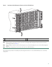
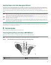
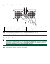
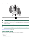
Figure 13 DC Power Supply Ground Studs and Cables
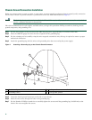
Step 4 Ground the other end of the grounding wires to an appropriate grounding point at your site.
Step 5 Repeat Steps 2 through Step 4 on the second DC power supply.
Wiring the DC-Input Power Source
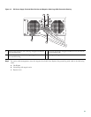
Note The color coding of the DC-input power supply leads depends on the color coding of the DC power source at your site.
Typically, green or green/yellow is used for ground (GND) on the power supply. Negative –48V black is on negative (–)
terminal and red is used for RTN on the positive (+) terminal. Make certain the lead color coding you choose for the
DC-input power supply matches lead color coding used at the DC power source.
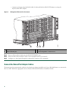
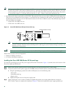
Step 1 Make sure the power switch circuit breaker is in the Off (O) position.
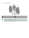
Step 2 Locate and remove the plastic cover from the terminal block.
1
Negative lug and wire with sleeving wrapped around the
wire and end of lug
3
Location of sleeving wrapped around the wire and end of
the grounding stud
2
Positive lug and wire with sleeving wrapped around the
wire and end of lug
4
Earth ground lug and wire
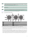
This unit might have more than one power supply connection. All connections must be removed to de-energ
OFF
-48/-60V 40A
280024
1 2
4
3