


39
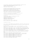
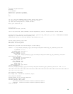
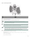
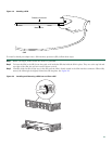
Figure 18 DC Power Supply Terminal Block
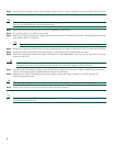
Step 6 Locate the power supply ground stud. Remove the earth ground (GND) cable from the power supply. For DC power
supply ground stud, see Figure 13.
Step 7 Loosen and remove the Kepnut screw, washer, and ground lug in that order.
Warning
When installing the unit, the ground connection must always be made first and disconnected last.
Step 8 Loosen the captive screws on the DC power supply.
Note Two power supplies must be installed in the chassis at all times to ensure sufficient cooling. The system fans are inside
the power supply units and must spin for cooling. Because all the system fans can be powered by one power supply, the
second power supply unit does not have to be powered on, but it must be installed.
Caution If you remove a power supply, the system can run for a maximum of five minutes before the system shuts down.
The fans and power elements are independent within the power supply. Therefore, it is not required that the
replacement power supply be energized within five minutes. The only requirement is that the power supply be
installed in the chassis, which energizes the fans and maintains proper system cooling.
Step 9 Grasping the power supply handles, pull the power supply from the chassis. When you remove the DC power supply,
you will see the following type of messages in the log report:
6ru_perf2#show log
Syslog logging: enabled (0 messages dropped, 6 messages rate-limited, 0 flushes, 0 overruns, xml
disabled, filtering disabled)
No Active Message Discriminator.
No Inactive Message Discriminator.
1
DC power supply terminal block negative lead stud
3
Plastic cover sloted and keyed area
2
DC power supply positive lead stud
4
DC power supply terminal block plastic cover
This unit might have mo
re than one power su
pply connection. All connections must be
remov
OFF
55
-48/-60V 40A
280027
3
4
1
2