


23
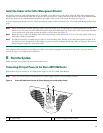
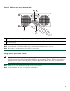
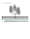
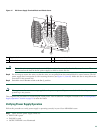
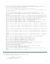
Figure 17 DC Power Supply Terminal Block and Plastic Cover
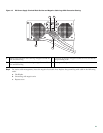
Caution Secure the wires coming in from the terminal block so that they cannot be disturbed by casual contact. There are
tabs located on the base of the DC power supply to which to secure the ties.
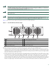
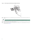
Step 8 Use tie wraps to secure the wires, so that the wires are not pulled from the terminal block by casual contact. The DC
power supply has tie-wrap tabs to aid in securing the wires (see Figure 11, item #3). Make sure the tie wrap allows for
some slack in the ground wire.
Step 9
Switch the circuit breaker switch to the On (|) position.
Note The requirement for maximum torque applied to the power or ground Kepnuts must be 8 in-lb when the power or
ground lug is not present.
This completes the procedure for connecting DC-input power. Your installation is complete. Proceed to the “Verifying Power
Supply Operation” section on page 23 to start the router.
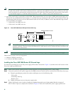
Verifying Power Supply Operation
Follow this procedure to verify power supply is operating correctly in your Cisco ASR10006 router.
Step 1 Check that the power supply LEDs are:
• INPUT OK is green
• FAN OK is green
• OUTPUT FAILED is not illuminated
1
Negative lead
3
Plastic cover slotted area
2
Positive lead
4
Terminal block plastic cover
This unit might have mo
re than one power supply connection. All connections must be
remov
OFF
55
-48/-60V 40A
280027
3
4
1
2