


D M S -100 CompuCALL Interface Specification (Q218) 49
49
49
Formula 3:
TotalBytesPC = MsgPC * Bmsta
Where: MsgPC - average CompuCALL messages per call
(message/call).
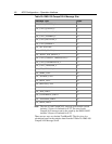
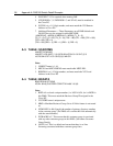
The other is to identify typical call scenarios and the most frequently used
CompuCALL messages, and obtain the size of these messages from the
X
Table 20: D M S-100 CompuCALL Message Size
X
.
Formula 4:
TotalBytesPC = MsgLen1 + MsgLen2 ¬ + …… + MsgLenn
Where: MsgLeni - is the message length of i-th CompuCALL message in
one call (bytes/call).
For example, when a SoftPhone application uses Third Party Call Control
(TPCC) and Third Party Agent Control (TPAC) to answer an incoming
ACD call, the CompuCALL message sequence is:
DV_CALL_OFFERED_U, DV_ANSWER_CALL ,
DV_CALL_ANSERED_U, DV_RELEASE_CALL,
DV_CALL_RELEASED_U, DV_SET-FEATURE,
DV_AGENT_NOT_READY_U, DV_SET-FEATURE,
DV_AGENT_READY_U.
By looking up the message length for each CompuCALL message in the
XTable 20: DMS-100 CompuCALL Message SizeX.
TotalBytesPC = 98 + 69 +64 + 69 + 70 + 70 + 45 + 70 + 45 = 600
(byte/call)
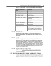
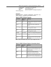
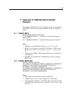
The designed capacity of the DMS-100 PG is listed as the following:
Table 21: DM S -100 Peripheral Gateway Capacity
Parameter
Maximum
Value
Meaning
PGSN
max
8
Maximum configured
CompuCALL sessions per switch.
PGLN
max
8
Maximum configured
CompuCALL links per
CompuCALL session.
The following formula can help you calculate the required number of the
CompuCALL links.
Formula 5:
TotalLinks = (nSVC * BandWidth ) / LinkBD
Where: TotalLinks - is the required number of CompuCALL links based on
call rate, call scenarios, occupancy of link, and etc.