


Contents v
v
v
Tables
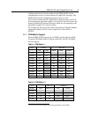
Table 1: CCM Matrix_1 ........................................................................................ 13
Table 2: CCM Matrix_2 ........................................................................................ 13
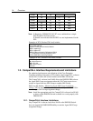
Table 3: DMS-100 PG Label Format ................................................................... 20
Table 4: CompuCALL Session Parameters ......................................................... 20
Table 5: CompuCALL Link Parameters ............................................................... 21
Table 6: Extension Formats ................................................................................. 24
Table 7: Param String Formats ............................................................................ 25
Table 8: CompuCALL Server Setup Options ....................................................... 29
Table 9: ACD Link Setup Options ........................................................................ 32
Table 10: Session Object Setup Options ............................................................. 33
Table 11: Application Link Setup Options ............................................................ 35
Table 12: Application Configuration Options........................................................ 36
Table 13: Example of Walk-Away Codes ............................................................. 37
Table 14: Unified ICM to DMS-100 Service Mapping .......................................... 40
Table 15: Unified ICM to DMS-100 Skill Group Mapping ................................... 41
Table 16: Unified ICM to DMS-100 Agent Mapping ............................................. 42
Table 17: CompuCALL Events to Cisco Agent State Mapping............................ 43
Table 18: DMS-100 Switch Capacity ................................................................... 47
Table 19: DMS-100 Switch Statistics Provided by Nortel .................................... 47
Table 20: DMS-100 CompuCALL Message Size................................................. 48
Table 21: DMS-100 Peripheral Gateway Capacity .............................................. 49
Figures
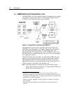
Figure 1: CompuCALL Interface with DMS100 .................................................... 12
Figure 2: Peripheral Monitor Configuration Window ............................................ 23
Figure 3: Peripheral Monitor Configuration with Parameter String ...................... 24
Figure 4: CompuCALL Session: Simple Case ..................................................... 26
Figure 5: CompuCALL Session: Complex Case .................................................. 28
Figure 6: CompuCALL Server Setup ................................................................... 29
Figure 7: ACD Link Setup .................................................................................... 31
Figure 8: Session Object Setup ........................................................................... 33
Figure 9: Application X.25 Link Setup .................................................................. 35
Figure 10: Application Configuration .................................................................... 36