


1-8
Cisco IE 3010 Switch Hardware Installation Guide
78-19581-02
Chapter 1 Product Overview
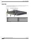
Cable Side
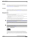
LEDs
You can use the switch system and port LEDs to monitor switch activity and performance.
Switch Panel LEDs
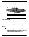
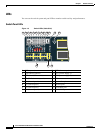
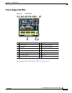
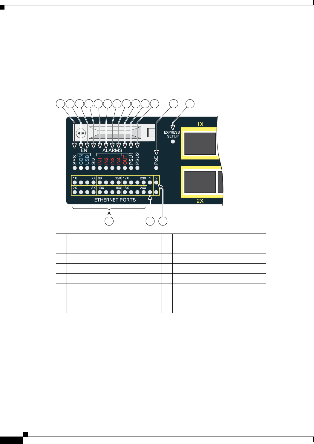
Figure 1-6 Switch LEDs (Cable Side)
1 SYS (system) 9 OUT (alarm output)
2 CON (RJ-45 console) 10 PSU1 (power supply 1)
3 USB (mini-USB console) 11 PSU2 (power supply 2)
4 SD (SD flash memory card) 12 PoE
1
1. Only on the Cisco IE-3010-16S-8PC switch.
5 IN1 (alarm input 1) 13 Express Setup button
6 IN2 (alarm input 2) 14 Ethernet ports
7 IN3 (alarm input 3) 15 SFP module port
8 IN4 (alarm input 4) 16 10/100/1000 port
207198
21 3 45678 9 10 11 12 13
14 15
16