


3-6
Cisco IE 3010 Switch Hardware Installation Guide
78-19581-02
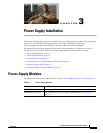
Chapter 3 Power Supply Installation
Power-Supply Module Installation
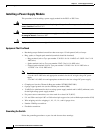
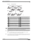
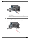
Figure 3-4 Crimping the Terminal Lug
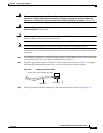
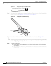
Step 4 Slide the ground screw from Step 1 through the terminal lug. Insert the ground screws into the opening
on the cable side.
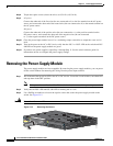
Figure 3-5 Attaching the Terminal Lug
Step 5 Use a ratcheting torque screwdriver to tighten the ground screws to 30 in-lb (± 2 in-lb).
Step 6 Attach the other end of the ground wire to a grounded bare metal surface, such as a ground bus or a
grounded bare rack.
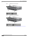
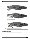
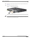
Installing the Power-Supply Module in the Switch
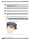
Step 1 We recommend that power be off at the AC or DC circuits. Locate the circuit breakers, turn them OFF,
and tape them in the OFF position.
Note If the power is not off at the AC or DC circuit breaker, do not touch the power-input terminal.
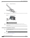
Step 2 Use a Phillips screwdriver to loosen the two captive screws of the blank power-supply module and gently
pull it out. See Figure 3-6 and Figure 3-7.
280938
1 Dual-hole terminal lug
Cisco IE 3010
208335