


3-9
Cisco IE 3010 Switch Hardware Installation Guide
78-19581-02
Chapter 3 Power Supply Installation
Power-Supply Module Installation
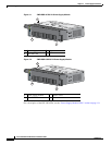
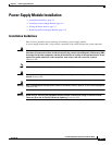
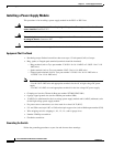
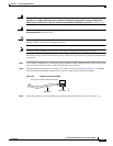
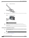
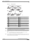
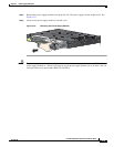
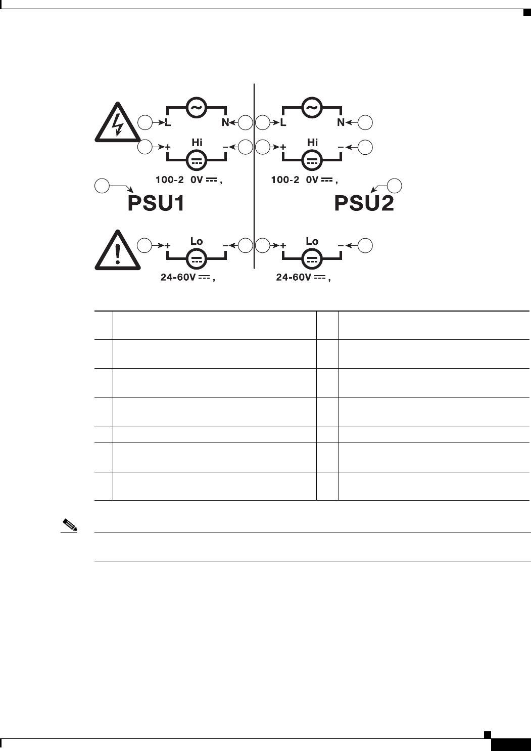
Figure 3-10 Power-Input Terminal
Note The power-supply module 1 connection is labeled PSU1, and the power-supply module 2 connection is
labeled PSU2. Make sure that you connect the wires to the correct terminal screws.
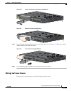
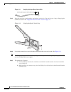
Step 3 Use twisted-pair copper wire (14- to 18-AWG) to connect from the power-input terminal to the power
source.
Note Use 12-AWG (minimum) for the low-voltage DC power supply module. Use 16-AWG
(minimum) for the high-voltage AC or DC power supply module.
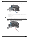
Step 4 Strip each of the two wires to 0.25 inch (6.3 mm) ± 0.02 inch (0.5 mm). Do not strip more than 0.27 inch
(6.8 mm) of insulation from the wire. Stripping more than the recommended amount of wire can leave
exposed wire from the connector after installation.
1
Line connection for high-voltage AC (PSU1) 8 Line connection for high-voltage AC (for
PSU2)
2 Neutral connection for high-voltage AC
(PSU1)
9 Neutral connection for high-voltage AC
(PSU2)
3 Positive connection for high-voltage DC
(PSU1)
10 Positive connection for high-voltage DC
(PSU2)
4 Negative connection for high-voltage DC
(PSU1)
11 Negative connection for high-voltage DC
(PSU2)
5 PSU1 (power-supply module 1) 12 PSU2 (power-supply module 2)
6 Positive connection for low-voltage DC
(PSU1)
13 Positive connection for low-voltage DC
(PSU2)
7 Negative connection for low-voltage DC
(PSU1)
14 Negative connection for low-voltage DC
(PSU2)
100-240V~, 50-60Hz, 2A
5
100-240V~, 50-60Hz, 2A
2A2A
10A
10A
5
2
1
4
3
76
98
11
10
14
13
5
12
207241