


7-10
Cisco Intrusion Prevention System Appliance and Module Installation Guide for IPS 7.1
OL-24002-01
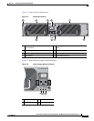
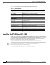
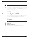
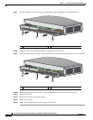
Chapter 7 Installing the IPS 4510 and IPS 4520
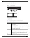
Accessories
Accessories
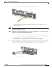
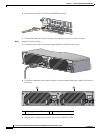
The contents of the sensor packing box contains the following items you need to install the sensor:
• Sensor chassis
• Documentation
• 2 Yellow Ethernet cables
• Blue console cable PC terminal adapter
• Power cable 120V
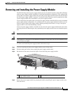
Note The IPS 4510 ships with one power supply module installed and one power cable. The IPS
4520, ships with two power supply modules installed and two power cables.
• Screws
• Cable management brackets
• Front and rear rack-mount brackets
• Slide rail kit hardware
• Slide rail kit
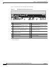
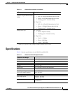
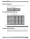
Maximum heat dissipation 3960 BTU/hr (100 VAC)
5450 BTU/hr (200 VAC)
Power supply output steady state
Maximum peak
1200W
1200W
Environment
Temperature Operating 32°F to 104°F (0°C to 40°C)
Nonoperating -40°F to 158°F (-40°C to 70°C)
Airflow Front to back
Relative humidity
(noncondensing)
Operating 10% to 90%
Nonoperating 5% to 95%
Altitude Operating 0 to 3000 ft (9843 ft)
Nonoperating 0 to 4570 ft (15,000 ft)
Shock Operating Half-sine 2 G, 11 ms pulse, 100 pulses
Nonoperating 15 G, 170 in/sec delta V
Vibration 2.2 Grms, 10 minutes per axis on all three axes
Noise 65 dBa max
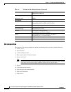
Table 7-4 IPS 4510 and IPS 4520 Specifications (continued)