


7-18
Cisco Intrusion Prevention System Appliance and Module Installation Guide for IPS 7.1
OL-24002-01
Chapter 7 Installing the IPS 4510 and IPS 4520
Removing and Installing the Power Supply Module
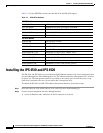
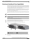
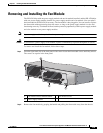
Step 5 Install the new power supply module by aligning it with the power supply module bay and pushing it
into place until it is seated.
Step 6 Tighten the captive screws.
Step 7 Reconnect the power cable. If you are installing two power supply modules for a redundant
configuration, plug each one into a power source (we recommend a UPS).
Step 8 If you had to power off the sensor because you are removing and replacing the only power supply
module, power it back on.
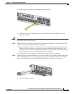
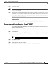
Step 9 Check the PS0 and PS1 indicators on the front panel to make sure they are green. On the back panel of
the sensor, make sure the IN OK and the FAN OK indicators are green and the OUT FAIL indicator is off.
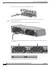
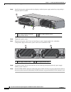
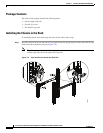
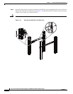
1 Power supply module and power
supply module handle
2 Power supply module screws
INPUT
OUTPUT
FAN
Cisco-ASA-FAN
Cisco ASA 1200W AC
100-240V
15.0/8.0.A
56/60Hz
IN
OK
FAN
OK
OUT
FAIL
Cisco ASA 1200W AC
100-240V
15.0/8.0.A
56/60Hz
IN
OK
FAN
OK
OUT
FAIL
253971
2
1
2
Cisco ASA 1200W AC
100-240V
15.0/8.0.A
56/60Hz
IN
OK
FAN
OK
OUT
FAIL
Cisco ASA 1200W AC
100-240V
15.0/8.0.A
56/60Hz
IN
OK
FAN
OK
OUT
FAIL
1 2
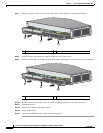
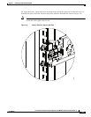
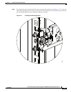
1 Power supply module (PS0) 2 Power supply module (PS1)