


7-14
Cisco Intrusion Prevention System Appliance and Module Installation Guide for IPS 7.1
OL-24002-01
Chapter 7 Installing the IPS 4510 and IPS 4520
Installing the IPS 4510 and IPS 4520
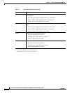
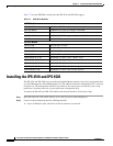
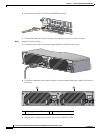
b. Connect one end of the LC cable to the SFP/SFP+ module.
c. Connect the other end of the LC cable to a network device, such as a router or switch.
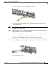
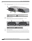
Step 5 Install the electrical cables.
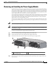
a. Attach the power cable to the power supply module on the back of the sensor.
b. If you have redundant power supply modules, you must connect both power cables to the back of
the sensor.
c. Plug the power cable(s) in to a power source (we recommend a UPS).
9
8
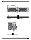
SFP/SFP+
7
6
253907
Cisco ASA 1200W AC
100-240V
15.0/8.0.A
56/60Hz
IN
OK
FAN
OK
OUT
FAIL
Cisco ASA 1200W AC
100-240V
15.0/8.0.A
56/60Hz
IN
OK
FAN
OK
OUT
FAI L
253972
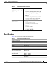
INPUT
OUTPUT
FAN
Cisco-ASA-FAN
Cisco ASA 1200W AC
100-240V
15.0/8.0.A
56/60Hz
IN
OK
FAN
OK
OUT
FAIL
Cisco ASA 1200W AC
100-240V
15.0/8.0.A
56/60Hz
IN
OK
FAN
OK
OUT
FAIL
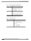
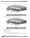
1 2
1 Power supply module (PS0) 2 Power supply module (PS1)