


7-5
Cisco Intrusion Prevention System Appliance and Module Installation Guide for IPS 7.1
OL-24002-01
Chapter 7 Installing the IPS 4510 and IPS 4520
Chassis Features
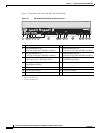
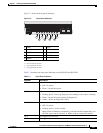
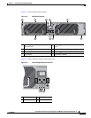
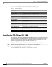
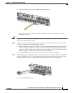
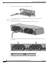
Figure 7-3 shows the front panel indicators.
Figure 7-3 Front Panel Indicators
Table 7-1 describes the front panel indicators on the IPS 4510 and IPS 4520.
1 PWR 2 BOOT
3 ALARM 4 ACT
1
1. Not supported at this time.
5 VPN
2
2. Not supported at this time.
6 PS1
7 PS0 8 HDD1
3
3. Not supported at this time.
9 HDD2
4
4. Not supported at this time.
PWR
BOOT
ALARM
ACT
VPN
PS1
HDD1
PS0
HDD0
USB
0
1
AUX CONSOLE
PWR
BOOT
ALARM
ACT
VPN
PS1
HDD1
PS0
HDD0
USB
0
1
AUX CONSOLE
253904
1
2
3
4
5
6
7
8
9
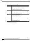
Table 7-1 Front Panel Indicators
Indicator Description
PWR Indicates whether the system is off or on:
• Off—No power.
• Green—System has power.
BOOT Indicates how the power-up diagnostics are proceeding:
• Flashing green—Power-up diagnostics are running or the system is booting.
• Green—System has passed power-up diagnostics.
• Amber—Power-up diagnostics failed.
ALARM Indicates whether a component has failed:
• Off—No alarm.
• Flashing yellow—Critical alarm.
Major failure of hardware component or software module, temperature over
the limit, power out of tolerance, or OIR is ready to remove the module.
1
ACT Not supported at this time.
VPN Not supported at this time.