


16
Cisco ME 6500 Series Ethernet Switch Installation Note
78-17360-02
Connecting the Power Supplies
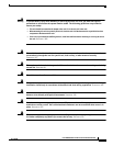
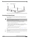
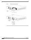
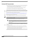
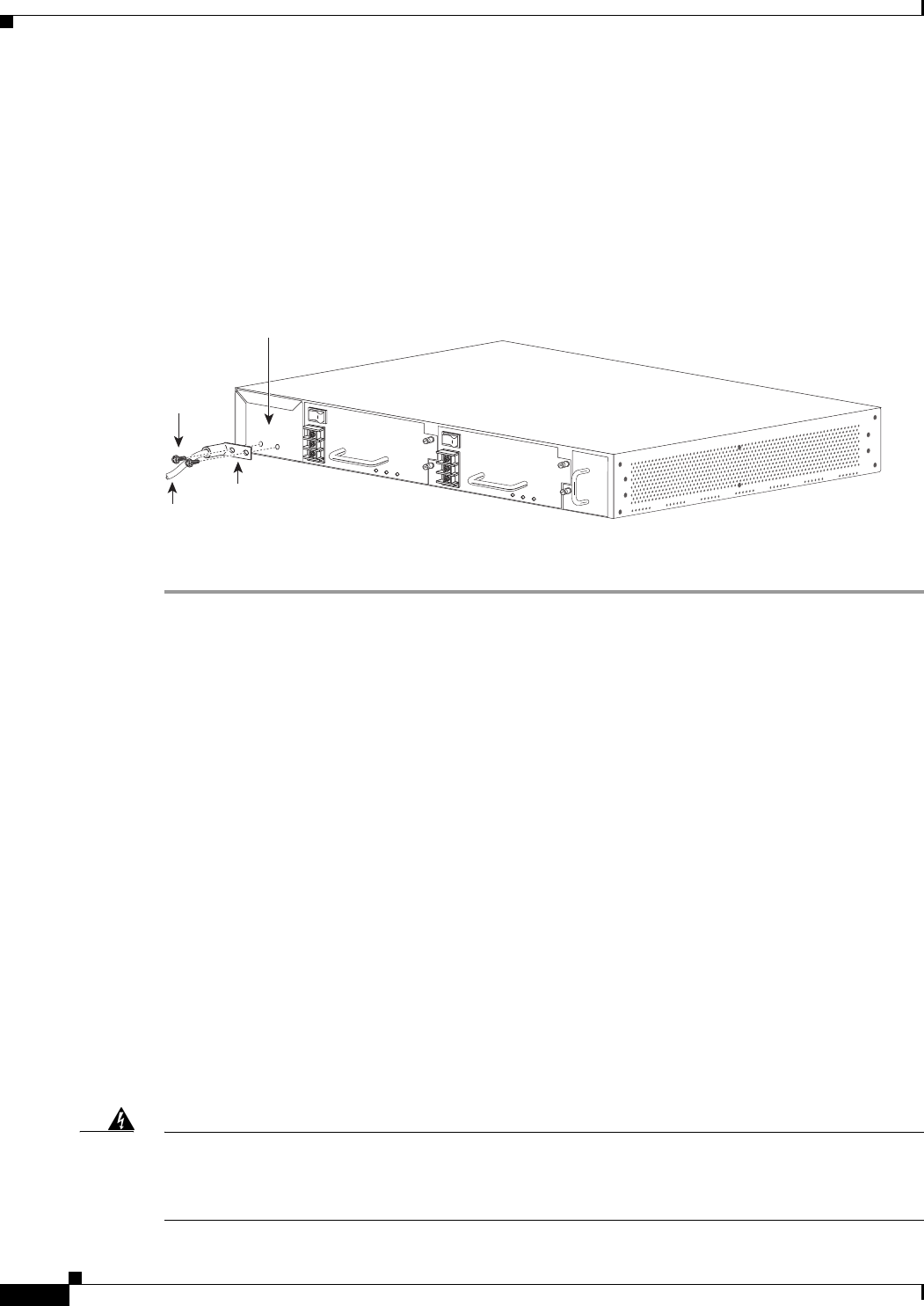
Step 3 Place the ground lug against the ground pad, making sure that there is solid metal-to-metal contact, and
secure it to the chassis with two M4 screws. Ensure that the ground lug and the ground wire do not
interfere with other cables or equipment.
Step 4 Prepare the other end of the system ground wire and connect it to an appropriate ground point in your
site to ensure adequate earth ground for the switch.
Figure 7 Attaching the System Ground
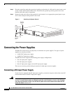
Connecting the Power Supplies
The ME 6524 switch chassis can physically accommodate two power supplies. Two types of power
supplies are currently available:
• A 400 W DC-input power supply
• A 400 W AC-input power supply
The ME 6524 chassis supports the following power supply configurations:
• Two AC-input power supplies
• Two DC-input power supplies
• One AC-input power supply and one DC-input power supply
The next two sections provide cabling instructions for both types of power supplies.
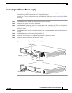
Connecting a DC-Input Power Supply
If your chassis is equipped with DC-input power supplies, you need to run power cables from source DC
to the terminal block on the DC-input power supply.
Warning
Before performing any of the following procedures, ensure that power is removed from the DC
circuits. To ensure that all power is removed, locate the circuit breakers or fuses on the DC power
lines that service the DC circuits. Turn OFF the DC power line circuit breakers and remove the DC
power line fuses.
Statement 322
147982
INPUT
OK
OUTPUT
OK
FAN
OK
INPUT
OK
OUTPUT
OK
FAN
OK
o
o
+
-
+
-
(M4)
Phillips-head
machine
screws
System
ground
pad
System
ground
wire
Ground
lug