


17
Cisco ME 6500 Series Ethernet Switch Installation Note
78-17360-02
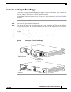
Connecting the Power Supplies
Warning
When installing or replacing the unit, the ground connection must always be made first and
disconnected last.
Statement 1046
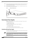
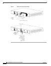
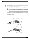
To attach source DC power cables to the DC-input power supply (see Figure 8), follow these steps:
Step 1 Verify that the system (NEBS) ground connection has been installed.
Step 2 Verify that power is off to the DC circuit that feeds the power supply that you are installing. As an added
precaution, place the appropriate safety flag and lockout devices at the source power circuit breaker, or
place a piece of adhesive tape over the circuit breaker handle to prevent accidental power restoration
while you are working on the circuit.
Step 3 Verify that the power switch is in the off (0) position on the power supply that you are connecting.
Step 4 Remove the clear plastic cover from the power supply terminal block and set it aside.
Step 5 Attach the appropriate size and style connectors to the source DC-input wires. The wire gauge size and
the connector size and type are determined by national and local electrical codes.
Note Either insulated crimp-on spade lugs or insulated crimp-on ring connectors can be used.
Step 6 Loosen the three terminal block screws and position the DC-input connectors under the screws in the
following order:
• Ground wire to the power supply ground terminal
• Negative (–) source DC cable to the power supply negative (–) terminal
• Positive (+) source DC cable to the power supply positive (+) terminal
Step 7 Tighten the three terminal block connections.
Step 8 Reinstall the power supply terminal block cover.
Caution To prevent a short circuit or shock hazard after wiring the DC-input power supply, you must reinstall the
terminal block cover.
Caution In a system with dual power supplies, connect each power supply to a separate power source. In case of
a power source failure to one supply, the second power source should still be available.
Step 9 Remove any safety flag and lockout devices or any tape from the circuit breaker switch handle, and
restore power by moving the circuit breaker switch handle to the on (|) position.
Note If a second power supply is not installed in the chassis, verify that the empty power supply bay has a
blank power supply filler plate (Cisco part number 800-27613-xx) installed over the opening, and that
the cover’s two captive installation screws are tightened.