


11
Supervisor Engine 720 Switch Processor and Route Processor Memory Installation Note
78-15538-02
Installing the SP and RP Memory Upgrade Kit
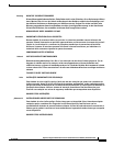
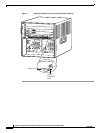
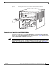
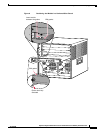
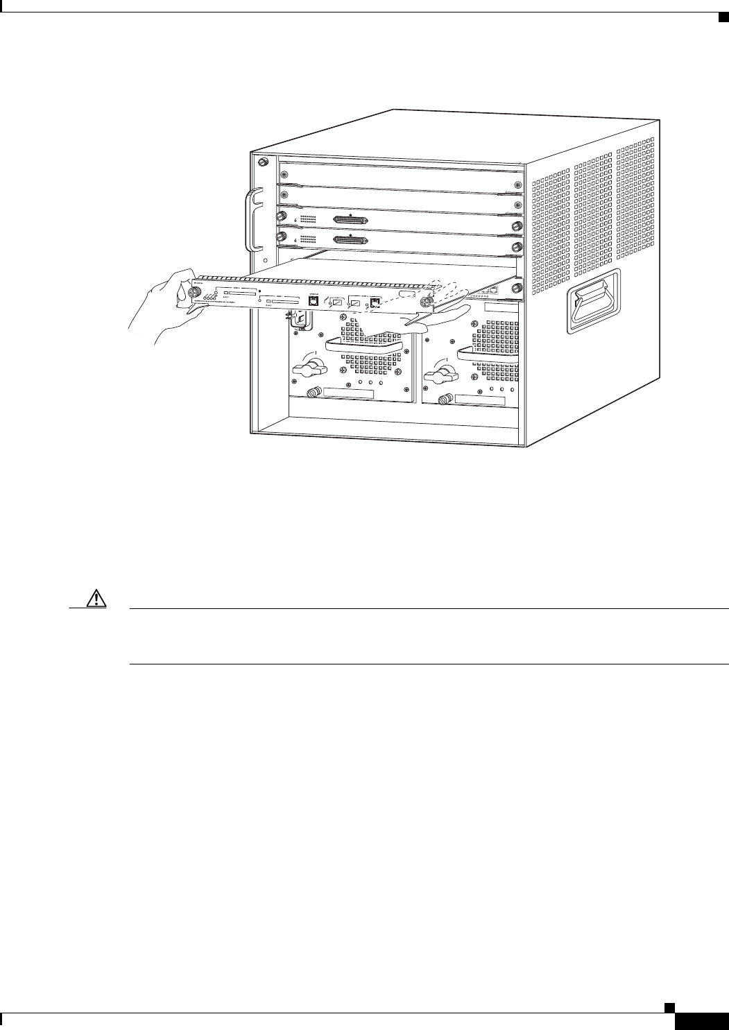
Figure 2 Removing the Module from the Chassis (Horizontal Chassis Shown)
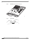
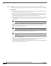
Removing and Installing the DRAM DIMMs
This section covers the removal of the old DRAM DIMMs and the installation of the DRAM DIMM
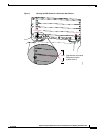
upgrade. There are two DRAM DIMMs that must be removed and replaced. Figure 3 shows the location
of the two DRAM DIMMs on the Supervisor Engine 720.
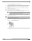
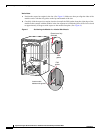
Caution The DRAM DIMM is a sensitive component that is susceptible to ESD damage. To prevent ESD damage,
wear an ESD grounding wrist strap, and handle the DIMM by the edges only; avoid touching the memory
modules, pins, or traces (the metal fingers along the connector edge of the DIMM). (See Figure 4.)
91526
INPUT
OK
FAN
OK
OUTPUT
FAI
L
o
INPUT
OK
FAN
OK
OUTPUT
FAI
L
o
1
2
3
4
5
6
WS
-X6624-FX
S
24 P
ORT F
XS AN
A
L
OG STA
TION
1
4
7
1
0
1
3
1
6
1
9
2
2
2
5
8
1
1
1
4
1
7
2
0
2
3
3
6
9
1
2
1
5
1
8
2
1
2
4
24
-1
STATUS
W
S
-X6624-FX
S
24
POR
T FXS A
NALO
G STA
TI
ON
1
4
7
1
0
1
3
1
6
1
9
2
2
2
5
8
1
1
1
4
1
7
2
0
2
3
3
6
9
1
2
1
5
1
8
2
1
2
4
24
-1
STATUS
4
8
P
O
R
T
1
0
/
1
0
0
B
A
S
E
-T
E
T
H
E
R
N
E
T
S
W
I
T
C
H
I
N
G
M
O
D
U
L
E
W
S
-
X
6
3
4
8
-
R
J
-
4
5
V
1
2
3
4
5
6
7
8
9
10
11
12
13
14
15
16
17
18
19
20
21
22
23
2
4
25
26
27
2
8
29
30
31
32
3
3
34
35
36
37
38
3
9
40
41
4
2
43
44
45
46
47
48
1
2
1
2
1
4
2
4
2
6
3
6
3
8
4
8