


16
Supervisor Engine 720 Switch Processor and Route Processor Memory Installation Note
78-15538-02
Installing the SP and RP Memory Upgrade Kit
Step 3 Depending on the orientation of the slots in the chassis (horizontal or vertical), perform one of the
following two sets of stepsfor positioning the module in a chassis with either horizontal or vertical slots:
Horizontal slots
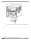
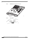
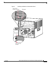
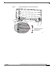
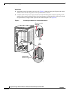
a. Position the supervisor engine in the slot. (See Figure 6.) Make sure that you align the sides of the
module carrier with the slot guides on each side of the slot.
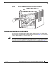
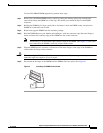
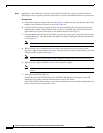
b. Carefully slide the supervisor engine into the slot until the EMI gasket along the top edge of the
module makes contact with the module in the slot above it and both ejector levers have closed to
approximately 45 degrees with respect to the module faceplate. (See Figure 7.)
c. Using the thumb and forefinger of each hand, grasp the two ejector levers, and press down to create
a small 0.040 inch (1 mm) gap between the supervisor engine’s EMI gasket and the module above
it. (See Figure 7.)
Note Do not press down too forcefully on the levers because they will bend and become damaged.
d. While pressing down, simultaneously close the left and right ejector levers to fully seat the
supervisor engine in the backplane connector. The ejector levers are fully closed when they are flush
with the module faceplate. (See Figure 7.)
Note Failure to fully seat the module in the backplane connector can result in error messages.
e. Tighten the two captive installation screws on the supervisor engine.
Note Make sure that the ejector levers are fully closed before tightening the captive installation
screws.
f. Verify that the STATUS LED is lit.
Periodically check the STATUS LED. If the STATUS LED changes from orange to green, the
module has successfully completed the boot process and is now online.
If the STATUS LED remains orange or turns red, the module has not successfully completed the boot
process and may have encountered an error.