


19
Supervisor Engine 720 Switch Processor and Route Processor Memory Installation Note
78-15538-02
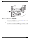
Installing the SP and RP Memory Upgrade Kit
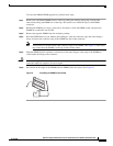
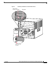
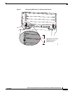
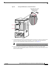
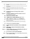
Figure 9 Clearing the EMI Gasket in a Vertical Slot Chassis
c.
Using the thumb and forefinger of each hand, grasp the two ejector levers, and exert a slight pressure
to the left, deflecting it approximately 0.040 inches (1 mm) creating a small gap between the
supervisor engine’s EMI gasket and the module adjacent to it. (See Figure 9.)
Note Do not exert too much pressure on the ejector levers because they will bend and be damaged.
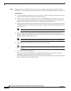
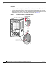
d. While pressing down on the ejector levers, simultaneously close the levers to fully seat the
supervisor engine in the backplane connector. The ejector levers are fully closed when they are flush
with the module faceplate.
INPUT
OK
FAN
OK
OUTPUT
FAIL
o
INPUT
OK
FAN
OK
OUTPUT
FAIL
o
4
8
4
8
FAN
STATUS
91530
Gap between the module
EMI gasket and the
module above it
1mm
Press left
Press left
SUPERVISOR 720 WITH INTEGRATED SWITCH FABRIC.
W
S
-S
U
P
7
2