


18
Supervisor Engine 720 Switch Processor and Route Processor Memory Installation Note
78-15538-02
Installing the SP and RP Memory Upgrade Kit
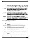
Vertical slots
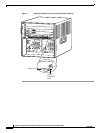
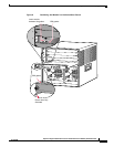
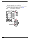
a. Position the supervisor engine in the slot. (See Figure 8.) Make sure that you align the sides of the
module carrier with the slot guides on the top and bottom of the slot.
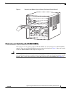
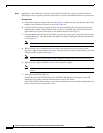
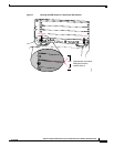
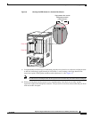
b. Carefully slide the supervisor engine into the slot until the EMI gasket along the right edge of the
module makes contact with the module in the slot adjacent to it and both ejector levers have closed
to approximately 45 degrees with respect to the module faceplate. (See Figure 9.)
Figure 8 Positioning the Module in a Vertical Slot Chassis
INPUT
OK
FAN
OK
OUTPUT
FAIL
o
INPUT
OK
FAN
OK
OUTPUT
FAIL
o
FAN
STATUS
Ejector lever fully
extended
4
3
6
S
E
L
E
C
T
N
E
X
T
24 PO
RT 100FX
WS-X6224
S
T
A
T
U
S
A
C
T
IV
E
EMI
gasket
EMI
gasket
91529
Insert module
between slot guides
4
8
4
8
SUPERVISOR 720 WITH INTEGRATED SWITCH FABRIC.
W
S
-S
U
P
7
2