


2-11
Catalyst 3560-C and 2960-C Switch Hardware Installation Guide
OL-23803-02
Chapter 2 Switch Installation
Mounting the Switch
Step 1 Locate the screw template. The template is used to align the mounting screw holes.
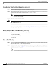
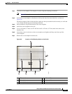
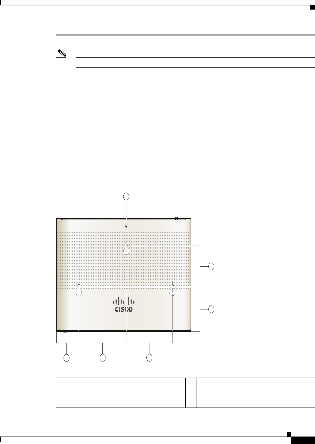
Note Figure 2-5 shows the measurements for the location of the screws on the switch.
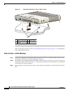
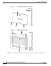
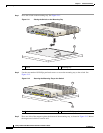
Step 2 Position the screw template so that the two side-by-side slots face toward the floor, as shown in
Figure 2-6.
For the best support of the switch and cables, make sure that you attach the switch securely to a wall stud
or to a firmly attached plywood mounting backboard.
Step 3 Peel the adhesive strip off the bottom of the screw template.
Step 4 Attach the screw template to the wall.
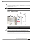
Step 5 Use a 0.144-inch (3.7 mm) or a #27 drill bit to drill a 1/2-inch (12.7 mm) hole in the three screw
template slots.
Step 6 Insert three screws in the slots on the screw template, and tighten until they touch the top of the
screw template.
Step 7 Remove the screw template from the wall.
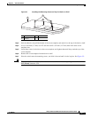
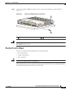
Figure 2-5 Location of the Mounting Holes on the Switch
1 1.77 in. (4.49 cm) 4 2.67 in. (6.78)
2 3.72 in. (9.44 cm) 5 2.46. in. (6.24)
3 3.62 in. (9.19 cm) 6 Switch
5
1
2
4
3
330380
6