


2-31
Catalyst 3560-C and 2960-C Switch Hardware Installation Guide
OL-23803-02
Chapter 2 Switch Installation
After Installing the Switch
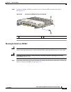
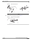
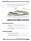
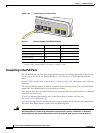
Step 5 (Optional) To attach the cable guard to the desk or wall, use a 0.144-inch (3.7 mm) or a #27 drill bit to
drill 1/2-inch (12.7 mm) holes at each of the two mounting locations. Insert the supplied 0.5 in.
(12.7 mm) number-8 Phillips wood screws and tighten them as shown in Figure 2-33.
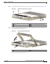
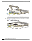
Figure 2-33 Securing the Cable Guard to the Desk
After Installing the Switch
1. Power on the switch. See the “Verifying Switch Operation” section on page 2-5.
2. Connect to a 10/100 or 10/100/1000 port, and run Express Setup. See the switch getting started guide
for instructions.
3. Connect to the ports. See the “Connecting Devices to the Ethernet Ports” section on page 2-33 to
complete the installation.
For configuration instructions about using the CLI setup program, go to Appendix C, “Configuring the
Switch with the CLI Setup Program.”
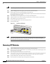
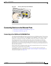
Installing SFP Modules
When installing SFP modules, observe these guidelines:
• Removing and installing an SFP module can shorten its useful life. Do not remove and insert any
module more often than is absolutely necessary.
• To prevent ESD damage, follow your normal board and component handling procedures when
connecting cables to the switch and other devices.
1 Number-8 Phillips wood screws 2 Desk or shelf
208919
2
11