


2-34
Catalyst 3560-C and 2960-C Switch Hardware Installation Guide
OL-23803-02
Chapter 2 Switch Installation
Connecting Devices to the Ethernet Ports
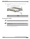
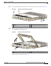
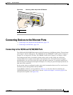
Figure 2-36 Connecting to an Ethernet Port
Connecting to the PoE Ports
The 10/100 PoE ports have the same autonegotiation settings and cabling requirements as those in the
“Connecting to the 10/100 and 10/100/1000 Ports” section on page 2-33. These ports provide PoE
power.
See the e “PoE Ports (Switches with PoE Ports)” section on page 1-5 for information on the cables and
connectors.
The ports provide PoE support for 802.3af-compliant devices and also provide Cisco prestandard PoE
support for Cisco IP Phones and Cisco Aironet Access Points.
On a per-port basis, you can control whether or not a port automatically provides power to a connected
IP phone or an access point.
To access an advanced PoE planning tool, use the Cisco Power Calculator on Cisco.com:
http://tools.cisco.com/20/launch.jsp
You can use this application to calculate the power supply requirements for a specific PoE configuration.
The results show output current, output power, and heat dissipation.
Warning
Voltages that present a shock hazard may exist on Power over Ethernet (PoE) circuits if
interconnections are made using uninsulated exposed metal contacts, conductors, or terminals.
Avoid using such interconnection methods, unless the exposed metal parts are located within a
Table 2-1 Ethernet Cables (Auto-MDIX Disabled)
Device Crossover Cable
1
1. 100BASE-TX and 1000BASE-T traffic requires twisted four-pair, Category 5, Category 5e, or
Category 6 cable. 10BASE-T traffic uses Category 3 or Category 4 cable.
Straight-Through Cable
1
Switch to switch Yes No
Switch to hub Yes No
Switch to computer or server No Yes
Switch to router No Yes
Switch to IP phone No Yes
1
2
Catalyst 2960-C
Series
PD
5678
208915