


2-13
Catalyst 3560-C and 2960-C Switch Hardware Installation Guide
OL-23803-02
Chapter 2 Switch Installation
Mounting the Switch
With a Mounting Tray
The mounting kit (part number CMP-MGNT-TRAY=) is optional. You can order it when you order your
switch, or you can order it later from your Cisco representative.
The mounting kit ships contents:
• Two number-10 Phillips pan-head screws
• Three number-8 Phillips pan-head screws
• Mounting tray
• Magnet
You can use the mounting tray by itself with mounting screws, or with a magnet.
Mounting Tray with Screws
You can use the mounting tray to secure the switch:
• On a desk or shelf
• Under a desk or shelf
• On a wall
Caution Do not wall-mount the switch with its front panel facing up. Following safety regulations, wall-mount
the switch with its front panel facing down or to the side, to allow sufficient airflow and to provide easier
access to the cables.
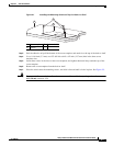
This example shows you how to mount the switch on a desk or shelf. You can use a similar procedure to
mount the switch under a desk or on a wall.
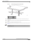
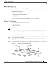
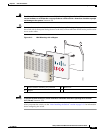
Step 1 Place the mounting tray on the desk.
Step 2 Use a 0.144-in. (3.7 mm) or a #27 drill bit to drill three 1/2-in. (12.7 mm) holes in the desk. See
Figure 2-8.
Step 3 Insert the three number-8 Phillips pan-head screws in the slots on the mounting tray, and tighten them.
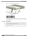
Figure 2-8 Attaching the Tray to the Desk or Shelf
3
2
1
1
1
208923