


2-19
Catalyst 3560-C and 2960-C Switch Hardware Installation Guide
OL-23803-02
Chapter 2 Switch Installation
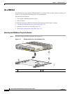
Mounting the Switch
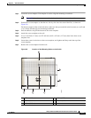
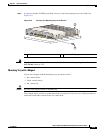
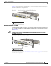
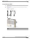
Figure 2-15 shows how to attach a 23-inch bracket to one side of the switch. Follow the same steps to
attach the second bracket to the opposite side.
Figure 2-15 Attaching the 23-inch Brackets for Rack-Mounting
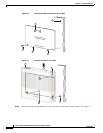
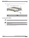
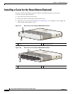
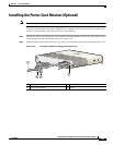
Mounting the Switch in a Rack
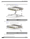
After the brackets are attached to the switch, insert the switch into the rack, and align the bracket in the
rack. Use either the number-12 or number-10 Phillips machine screws
to secure the switch in the rack.
See Figure 2-16.
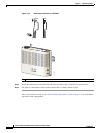
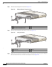
Warning
To prevent airflow restriction, allow clearance around the ventilation openings to be at least:
3 in. (7.6 cm)
Statement 1076
Figure 2-16 Mounting the Switch in a Rack
After you mount the switch, see the “After Installing the Switch” section on page 2-31 for information
about the switch configuration.
1 Phillips flat-head screw
M
ODE
C
O
NSOL
E
1
2
Se
r
ies
PD
POWE
R
O
V
E
R
ETHER
N
ET
1
2
345678
P
D
S
P
D
P
oE
DPLX
S
T
AT
S
Y
S
T
282400
1
1 Phillips machine screws
MODE
C
ON
S
O
L
E
1
2
Serie
s
P
D
P
OW
ER
OV
ER
ETH
E
R
N
E
T
12
34
5678
P
D
SP
D
P
o
E
D
P
LX
STAT
SYST
282402
1