


4-20
Data Center High Availability Clusters Design Guide
OL-12518-01
Chapter 4 FCIP over IP/MPLS Core
Testing Scenarios and Results
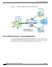
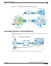
When a PE router forwards a packet received from a CE router across the provider network, it labels the
packet with the label learned from the destination PE router. When the destination PE router receives the
labeled packet, it pops the label and uses it to direct the packet to the correct CE router. Label forwarding
across the provider backbone is based on either dynamic label switching or traffic engineered paths.
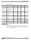
A VRF contains the routing information that defines the customer VPN site that is attached to a PE
router. It consists of the following elements:
• An IP routing table
• A derived CEF table
• A set of interfaces that use the forwarding table
• A set of rules and routing protocols that determine what goes into the forwarding table
Testing Scenarios and Results
Test Objectives
This section describes the testing performed to simulate an IP/MPLS network and to transport FCIP
traffic across the simulated SP network. The test objectives were as follows:
• Transporting FCIP traffic (from the customer location) using the Cisco MDS 9216i as the FCIP
gateway across IP/MPLS
• Verifying throughput across IP/MPLS
• Verifying whether the traffic can be passed without any errors, including VSANs
• Assessing the impact of core failover
• Assessing the impact of maximum transmission unit (MTU) size
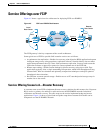
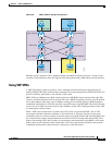
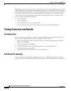
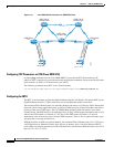
Lab Setup and Topology
Figure 4-10 shows the test lab setup, which consists of two Cisco MDS 9216s connected to the PE
routers (Cisco 7500 and GSR) running MPLS. The PEs connect to the core GSR boxes running MPLS.