


4-8
Data Center High Availability Clusters Design Guide
OL-12518-01
Chapter 4 FCIP over IP/MPLS Core
Using FCIP Tape Acceleration
FCIP Tape Acceleration maintains data integrity in the event of a variety of error conditions. Link errors
and resets are handled through Fibre Channel-tape Ethernet LAN services (ELS) recovery mechanisms.
Should the remote tape unit signal an error for an I/O that the status has already been returned to “good”,
a Deferred Error is signaled to the tape backup application. The backup application either corrects the
error and replays the command or rolls back to the previous file mark and replays all I/Os from that point.
You can enable FCIP Tape Acceleration on any FCIP interface on the Cisco IPS-4, IPS-8, and MPS-14/2
modules, or the Gigabit Ethernet interfaces on the Cisco MDS 9216i.
FCIP
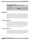
FCIP encapsulates Fibre Channel frames and transports these frames within TCP packets. The FCIP
tunnel acts as an Inter-Switch Link (ISL) between two fabric switches. The endpoint devices detect each
other as they would between two local switches interconnected with standard ISL. FCIP endpoints are
associated to virtual e-ports and these ports communicate with themselves and exchange information
such as reconfigure fabric (RCF), Fabric Shortest Path First (FSPF), build fabric (BF), and so on. FCIP
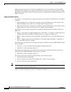
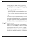
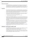
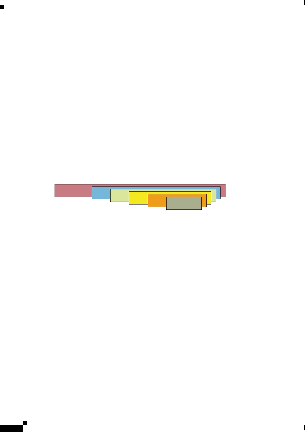
relies on the TCP/IP protocol to provide contention control and orderly delivery of packets. Figure 4-3
shows the FCIP encapsulation process.
Figure 4-3 FCIP Encapsulation
TCP Operations
TCP implemented on traditional servers or hosts tends to overreact to packet drops. The throttling back
that occurs in the traditional TCP implementation is not acceptable to storage traffic. The TCP stack
implemented for FCIP (in the Cisco MDS 9000) is optimized for carrying storage traffic by reducing the
probability of drops and increasing the resilience to drops when they occur.
Fibre Channel traffic can be highly bursty, and traditional TCP can amplify that burstiness. With
traditional TCP, the network must absorb these bursts through buffering in switches and routers. Packet
drops occur when there is insufficient buffering at these intermediate points. To reduce the probability
of drops, the FCIP TCP implementation reduces the burstiness of the TCP traffic that leaves the Gigabit
Ethernet interface.
In the FCIP TCP stack, burstiness is limited through the use of variable rate, per-flow shaping, and by
controlling the TCP congestion window size. After idle or partially idle periods, the FCIP interface does
not send large packet bursts at Gigabit interface speeds. If not controlled, large Gigabit Ethernet bursts
can overflow downstream routers or switches and speed mismatches can occur. For example, a Gigabit
Ethernet feeding into a DS3 (45 Mbps) link through a router may overflow the router buffers unless the
traffic is controlled or shaped in a way that the router can handle the transmission.
TCP Parameters
TCP parameters may require adjustments when implementing SAN extension that uses FCIP. This
section provides general information and recommendations for key TCP parameters that require
adjustments. The following parameters are considered:
132423
IP
TCP
FCIP
FC
SCSI
Data