


2-4
Catalyst 2940 Switch Hardware Installation Guide
OL-6157-01
Chapter 2 Installation
Verifying Switch Operation
• Regulatory Compliance and Safety Information for the Catalyst 2940 Switch
(order number DOC-7816656=)
• Product ownership registration card
If you want to connect a terminal to the switch console port, you need to provide an RJ-45-to-DB-25
female DTE adapter. You can order a kit (part number ACS-DSBUASYN=) with that adapter from Cisco.
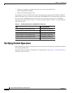
You can connect a 100BASE-FX port to an SC port on a target device by using one of the MT-RJ
fiber-optic patch cables listed in Table 2-1. Use the Cisco part numbers in Table 2-1 to order the patch
cables that you need.
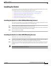
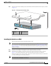
Verifying Switch Operation
Before installing the switch, you should power on the switch and verify that it passes POST as described
in the getting started guide.
The System LED turns amber if the POST fails. If the POST fails, see Chapter 3, “Troubleshooting,” to
determine a course of action.
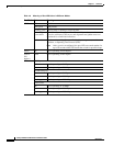
Table 2-1 MT-RJ Patch Cables for 100BASE-FX Connections
Type Cisco Part Number
1-meter, MT-RJ-to-SC multimode cable CAB-MTRJ-SC-MM-1M
3-meter, MT-RJ-to-SC multimode cable CAB-MTRJ-SC-MM-3M
5-meter, MT-RJ-to-SC multimode cable CAB-MTRJ-SC-MM-5M
1-meter, MT-RJ-to-ST multimode cable CAB-MTRJ-ST-MM-1M
3-meter, MT-RJ-to-ST multimode cable CAB-MTRJ-ST-MM-3M
5-meter, MT-RJ-to-ST multimode cable CAB-MTRJ-ST-MM-5M