


2-15
Catalyst 2940 Switch Hardware Installation Guide
OL-6157-01
Chapter 2 Installation
Connecting to the 100BASE-FX Port
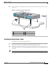
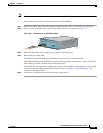
Step 2 Insert the other cable end into an RJ-45 connector on the target device.
Step 3 Observe the port status LED.
The LED turns green when the switch and the target device have an established link.
The LED turns amber while Spanning Tree Protocol (STP) discovers the network topology and searches
for loops. This process takes about 30 seconds, and then the LED turns green.
If the LED is off, the target device might not be turned on, there might be a cable problem, or there might
be a problem with the adapter installed in the target device. See Chapter 3, “Troubleshooting,” for
solutions to cabling problems.
Step 4 Reconfigure and restart the target device if necessary.
Step 5 Repeat Steps 1 through 4 to connect each port.
Connecting to the 100BASE-FX Port
The 100BASE-FX port on the Catalyst 2940-8TF-S operates only in full-duplex mode.
You can connect a 100BASE-FX port to an SC port on another device by using one of the MT-RJ
fiber-optic patch cables listed in Table 2-1 on page 2-4. Use the Cisco part numbers in Table 2-1 to order
the patch cables that you need.
Caution Do not remove the dust plugs from the fiber-optic ports or the rubber caps from the fiber-optic cable until
you are ready to connect the cable. The plugs and caps protect the fiber-optic ports and cables from
contamination and ambient light.
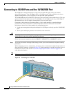
Follow these steps to connect the switch to a 100BASE-FX device:
Step 1 Remove the dust plugs from the 100BASE-FX port and the rubber caps from the MT-RJ patch cable.
Store them for future use.
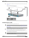
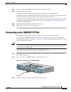
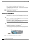
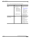
Step 2 Insert the cable in a 100BASE-FX port, as shown in Figure 2-10.
Figure 2-10 Connecting to a 100BASE-FX Port
Step 3
Insert the other cable end into an SC port on the target device.
89476
9
1
100Base-FX
SFP
1x
2x
3x
4x
5x
6x
7x
8x
Catalyst 2940
SERIES
S
Y
S
T
S
T
A
T
D
P
LX
S
P
D
M
O
D
E