


B-5
Catalyst 2940 Switch Hardware Installation Guide
OL-6157-01
Appendix B Connectors and Cables
Cable and Adapter Specifications
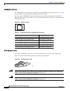
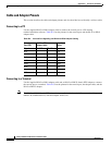
Console Port
The console port uses an 8-pin RJ-45 connector. You can connect a switch to a PC through the console
port and the supplied RJ-45-to-DB-9 adapter cable. If you want to connect a switch to a terminal, you
need to provide an RJ-45-to-DB-25 female DTE adapter. You can order a kit (part number
ACS-DSBUASYN=) with that adapter from Cisco. For console-port and adapter-pinout information, see
Table B-2 and Table B-3.
Cable and Adapter Specifications
These sections describe the cables and adapters used with Catalyst 2940 switches.
• Two Twisted-Pair Cable Pinouts, page B-5
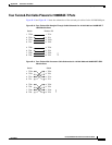
• Four Twisted-Pair Cable Pinouts for 10/100 Ports, page B-6
• Four Twisted-Pair Cable Pinouts for 1000BASE-T Ports, page B-7
• Cable and Adapter Pinouts, page B-8
Two Twisted-Pair Cable Pinouts
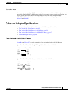
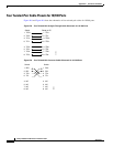
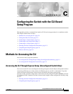
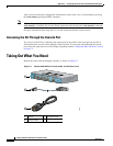
Figure B-6 and Figure B-7 show the schematics of two twisted-pair cables for 10/100 ports.
Figure B-6 Two Twisted-Pair Straight-Through Cable Schematic for 10/100 Ports
Figure B-7 Two Twisted-Pair Crossover Cable Schematic for 10/100 Ports
Switch
3 TD+
6 TD–
1 RD+
2 RD–
Router or PC
3 RD+
6 RD–
1 TD+
2 TD–
H5578
Switch
3 TD+
6 TD–
1 RD+
2 RD–
Switch
3 TD+
6 TD–
1 RD+
2 RD–
H5579