


PA-T3 Port Adapter LEDs
PA-T3 Serial Port Adapter Installation and Configuration
2-4
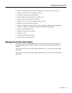
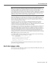
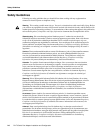
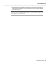
Figure 2-1 LEDs on the PA-T3 Serial Port Adapter—Partial Front View
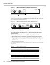
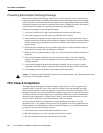
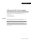
The PA-2T3 has one status LED and six uplink port status LEDs (RCLK, FERF, OOF, AIS, RL, and
LL) for each serial PA-T3 port. (See Figure 2-2.)
Figure 2-2 LEDs on the PA-2T3 Serial Port Adapter—Partial Front View
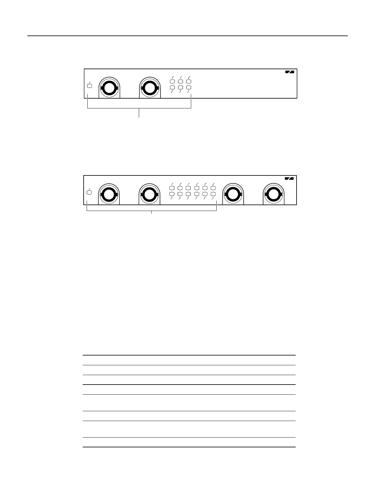
Table 2-2 describes the PA-T3’s LEDs.
After system initialization, the Enabled LED goes on, indicating that the port adapter has been
enabled for operation.
The following conditions must be met before the PA-T3 serial port adapter is enabled:
• The port adapter contains a valid microcode version that has been downloaded successfully.
• The port adapter is correctly connected to the VIP2 or Catalyst RSM/VIP2 (Cisco 7000 series
and Cisco 7500 series,or Catalyst 5000 series switches) and the midplane and is receiving power
in the Cisco router.
• The bus recognizes the port adapter.
If any of these conditions is not met or if the initialization fails for other reasons, the enabled LED
does not go on.
Table 2-2 LEDs for Uplink Port Status
LED Color State Description
ENABLED Green On Indicates that port adapter is ready for operation.
Uplink Port Status
RCLK Green On Indicates that a receive clock has been detected.
FERF Yellow On Indicates that Framer detected Far End Receive
Failure.
OOF Yellow On Indicates that Framer detected Out of Frame.
AIS Yellow On Indicates that Framer detected Alarm Indication
Signal.
RL Yellow On Indicates that port is in remote loopback mode.
ENABLED
RCVR
XMTR
RCLK
AIS
FERF
RL
OOF
LL
DS3 SERIAL
H10040
LEDs
ENABLED
RCVR
XMTR
RCLK
AIS
FERF
RL
RCLK
FERF
RL
OOF
LL
AIS
OOF
LL
DS3 SERIAL
H10063
LEDs