


Installing a Port Adapter
PA-T3 Serial Port Adapter Installation and Configuration
3-6
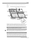
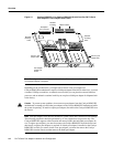
Caution To prevent jamming the carrier between the upper and the lower edges of the port adapter
slot and to ensure that the edge connector at the rear of the port adapter mates with the connector at
the rear of the port adapter slot, make certain that the leading edges of the carrier are between the
upper and the lower slot edges, as shown in the cutaway in Figure 3-5.
Caution To ensure a positive ground attachment between the port adapter carrier and the VIP2
motherboard and port adapter slot, and to ensure that the connectors at the rear of the port adapter
and slot mate properly, position the carrier between the upper and the lower slot edges, as shown in
Figure 3-5.
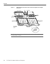
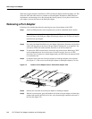
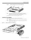
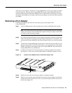
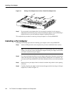
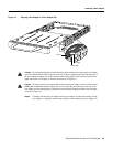
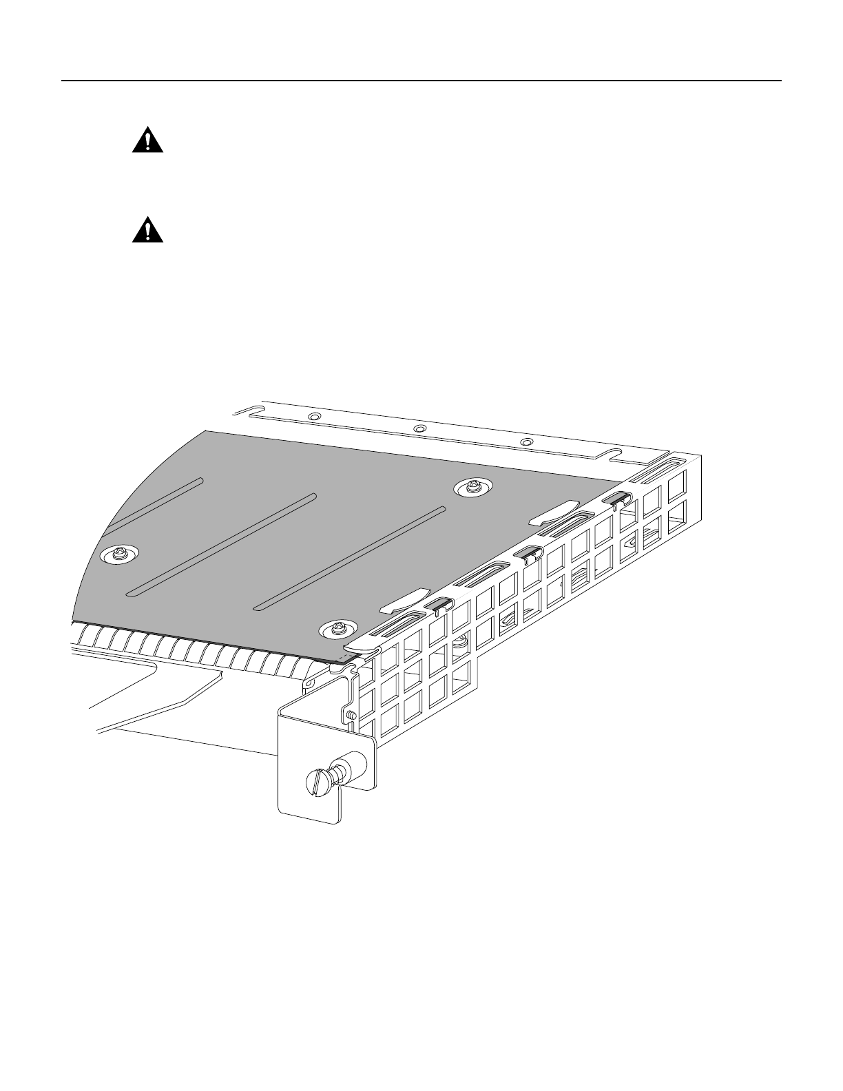
Step 3 Carefully slide the new port adapter into the port adapter slot until the connector on the
port adapter is completely seated in the connector on the motherboard. (See Figure 3-6.)
Figure 3-6 Port Adapter Installed in a Port Adapter Slot—Partial Port Adapter View
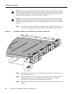
Step 4 Replace the screw in the rear of the port adapter slot. (See Figure 3-3 for its location.) Do
not overtighten this screw.
Step 5 Reinstall the VIP2 in the system. (Follow the steps in the section “Installing a VIP2” in
the configuration note Second-Generation Versatile Interface Processor [VIP2]
Installation and Configuration, which shipped with your VIP2.)
Step 6 If the interface cables have been disconnected, reconnect the interface cables to the port
adapters.
H3152