


2-3
Cisco SFS 3012R Multifabric Server Switch Hardware Installation Guide
OL-11187-01
Chapter 2 Installing and Booting the Cisco SFS 3012R Server Switch
Preparing for Installation
Preparing for Installation
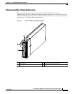
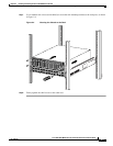
Warning
Two people are required to lift the chassis. Grasp the chassis underneath the lower edge and lift with
both hands. To prevent injury, keep your back straight and lift with your legs, not your back. To prevent
damage to the chassis and components, never attempt to lift the chassis with the handles on the
power supplies or on the interface processors, or by the plastic panels on the front of the chassis.
These handles were not designed to support the weight of the chassis.
Statement 5
Prepare for your installation by unpacking the product, and ensuring other necessary components are
available, as described in the following steps.
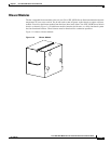
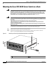
Step 1 Remove all components from the Cisco SFS 3012R Server Switch shipping container, and identify them.
Step 2 Place the chassis on a secure, clean surface.
Step 3 Verify that you have a Cisco SFS 7008 InfiniBand and Cisco SFS 3012 Multifabric Server Switches
Shelf Kit at hand (ordered and shipped separately, product number SFS-7008P-RKIT).
Step 4 Verify that you have at hand all Ethernet gateways and Fibre Channel gateways that you will need to
increase the port count of your Cisco SFS 3012R Server Switch.
Step 5 Prepare a management workstation (not included), such as a PC running terminal-emulation software
(not included), and a straight-through M/F DB-9 serial cable (included).
Installing Cisco SFS 3012R Server Switch Components
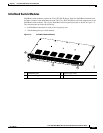
We recommend that you install all Ethernet or Fibre Channel gateway modules before you mount the
Cisco SFS 3012R Server Switch, as described in the “Adding or Replacing Ethernet or Fibre Channel
Gateways” section on page 3-3. These components are not preinstalled in the Cisco SFS 3012R Server
Switch chassis. However, you can add or change modules after mounting the Cisco SFS 3012R Server
Switch chassis in the rack. For details about installing Fibre Channel gateways, see the Cisco SFS 3000
Series Product Family Fibre Channel Gateway User Guide. For details about installing Ethernet
gateways, see the Cisco SFS 3000 Series Product Family Ethernet Gateway User Guide.
Note All cable connections to Ethernet gateways must use shielded RJ45 CAT5 Ethernet cables.
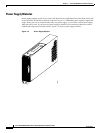
All other server switch modules are preinstalled in your Cisco SFS 3012R Server Switch before
shipping. You can, if needed, still add or replace these components before mounting the
Cisco SFS 3012R Server Switch chassis. These components include the following:
• Switch modules
• Controller modules
• Power supplies
• Blower modules
Instructions for installing or replacing these components appear in Chapter 3, “Installing and Removing
Server Switch Field Replaceable Units (FRUs)”.