


13
Cisco SFS 3504 Multifabric Server Switch Installation and Configuration Note
78-18335-01
Configuring the Cisco SFS 3504 Server Switch
Obtaining an IP Address from the DHCP Server for Ethernet Management
This section describes how to obtain an IP address from the DHCP server by default.
Note DHCP is enabled by default on the Cisco SFS 3504 Server Switch.
To obtain an IP address using the default enabled DHCP, you must obtain the MAC address. The MAC
address is printed on a label on your Cisco SFS 3504 Server Switch in the following format:
AA:BB:CC:DD:EE.
Use the MAC address to configure your DHCP server to allocate an IP address of your choice to the
SFS 3504 switch management interface. Otherwise, the DHCP server (if present) allocates the first
available IP address from the designated pool of addresses. In the latter case you can find out which
address was allocated by logging in to the CLI on the serial console and entering the show interface
mgmt-eth command. See the Cisco SFS Product Family Command Reference for additional details
about CLI commands.
Use the IP address, to Telnet to the Cisco SFS 3504 Server Switch and perform tasks such as configuring
the system clock and configuring an NTP server as described in the “Configuring the System Clock”
section on page 17 and “Configuring an NTP Server” section on page 18.
Configuring a Static IP Address for Ethernet Management
Note If a DHCP server is not available, then use this method to configure an IP address.
To configure a static IP address for an Ethernet Management interface, you must first connect the serial
console port. You can connect the serial console port to a PC serial port for local administrative access
to the Cisco SFS 3504 Server Switch. A terminal emulation software product, such as HyperTerminal,
makes communication between the Cisco SFS 3504 Server Switch and your PC possible during setup
and configuration.
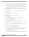
To connect the console port to a PC, perform the following steps:
Step 1 Connect the cable from the serial console port on the controller module, located on the rear panel of the
Cisco SFS 3504 Server Switch, to your terminal or management workstation. Use the straight-through
M/F serial cable, which is provided in the package.
Step 2 Open a terminal emulation window using a program such as Hyper-Terminal for Windows.
Step 3 Configure the baud rate and character format of the PC terminal emulation program to match the
following management port default characteristics:
• Baud: 9600 bps
• Data Bits: 8
• Parity: None
• Stop Bits: 1
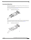
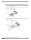
Step 4 Connect the supplied DB-9/RJ-45 female adapter or DB-25/RJ-45 female adapter (depending on your
PC connection) to the PC serial port.