


7
Cisco SFS 3504 Multifabric Server Switch Installation and Configuration Note
78-18335-01
Installing the Cisco SFS 3504 Server Switch
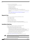
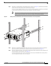
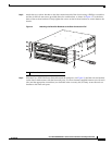
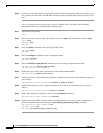
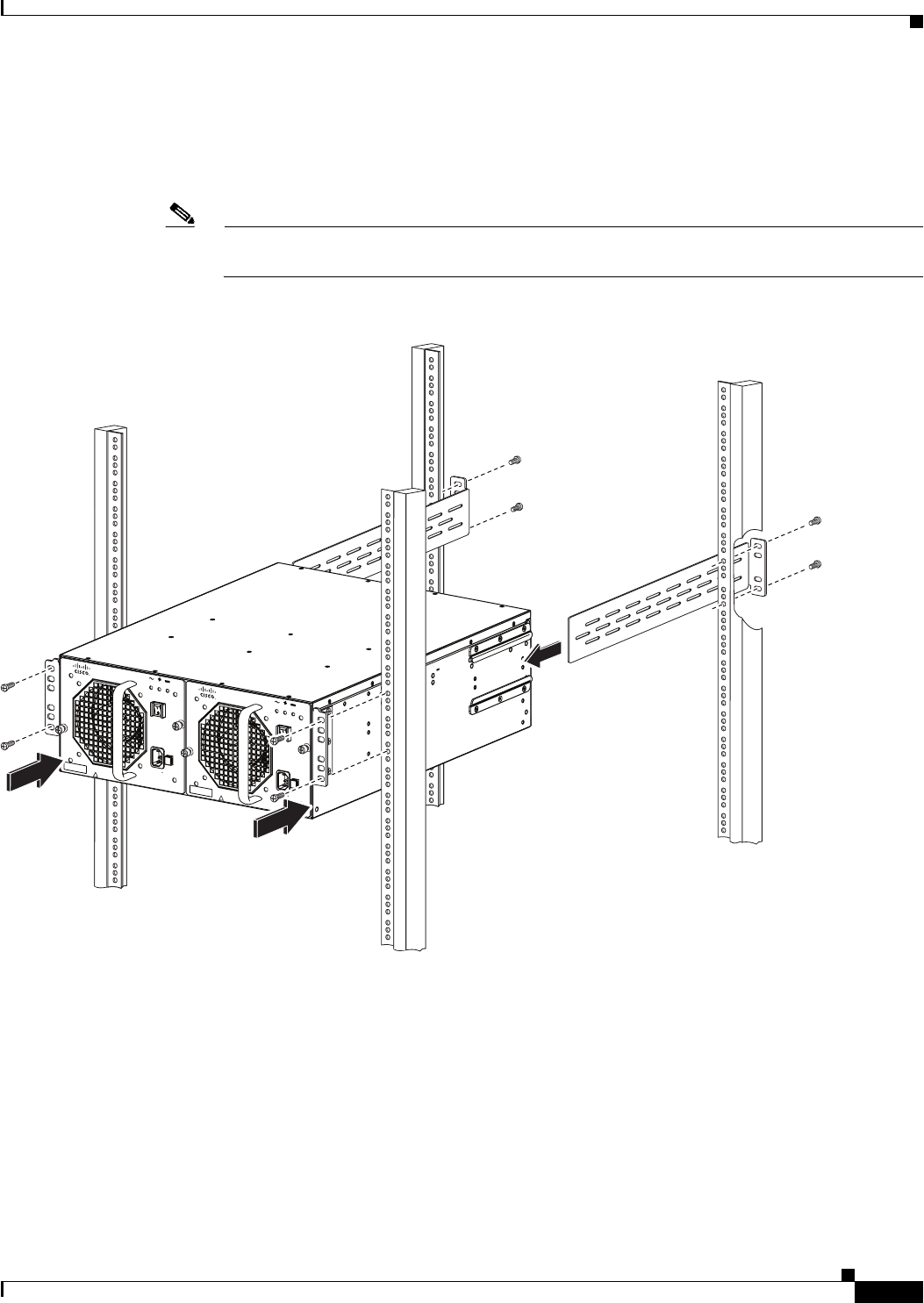
Step 3 Slide the Cisco SFS 3504 Server Switch between the rack posts (see Figure 2), until the rack ear brackets
on the front of the chassis make contact with the front rack posts.
Use four customer-supplied fasteners (two for each side) and the appropriate screwdriver (not included
in the accessory kit) to firmly secure the rack ear brackets to the front rack posts.
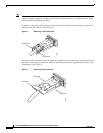
Note The handle on the AC power-fan module and/or the blanking panel can be used as an aid to
support the power-fan module side of the chassis during rack-mounting installation.
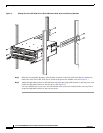
Figure 2 Sliding the Cisco SFS 3504 Server Switch Between Rack Posts and Inserting Brackets
Step 4
Slide the two adjustable brackets, from the back, between each of the guide rails that are attached on
either side of the Cisco SFS 3504 Server Switch at the data connection end. (See Figure 2.)
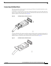
Step 5 Adjust the adjustable brackets so that the holes in the brackets align with the holes in the rack posts, and
secure the brackets to the rack posts. (See Figure 2.)
Use four standard rack screws (two for each bracket; rack screws not included in the accessory kit) to
secure the adjustable brackets to the rear rack posts.
241649
INPUT
OK
FAN
OK
OUTPUT
FAIL
SFS3500
Series
CAUT
ION: DISCONNECT PO
WER BEFOR
E SERVICING
!
ALL FASTENERS MUST
BE
FULLY ENGA
GED PRI
OR
TO
OPERA
TION OF POWER SUPP
LY
100-240V
8-4A
50/60
Hz
INPUT
OK
FAN
OK
OUTPUT
FAI
L
SFS3500
Series
CAUT
ION: DISCONNECT POWER BEFORE S
ERVI
CING
!
ALL F
AST
ENERS MUST
BE
FULL
Y EN
GAGED PRIOR TO
OPE
RAT
ION OF P
OWER SUP
PLY
100-240V
8-4A
50/60H
z