


TD 92322GB
2007-06-26/ Ver. D
Installation and Operation Manual
Integrated Message Server, IMS/IP-WiFi
13
3 Enter the address 127.0.0.1/BAM in one address field. Click the “Activate” button.
Configuration of Alarm and User Data
1 Open the IMS/IP administration pages and click “Message Distribution” for the
WLAN Interface.
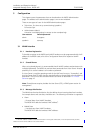
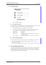
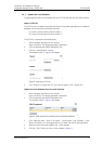
2 Click “Alarm”, see figure 6.
Figure 6. Setting up the Message Distribution list for the WLAN Interface to send
information to the Basic Alarm Manager.
3 Enter the address 127.0.0.1/BAM in one address field. Click the “Activate” button.
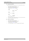
4 Click “Message Distribution” for the WLAN Interface.
5 Click “Mobile Data”.
6 Enter the address 127.0.0.1/BAM in one address field. Click the “Activate” button.
6.4 Configuration
The Basic Alarm Manager can be reached from the left menu in the IMS/IP administration
pages and also from the direct link http://xxx.xxx.xxx.xxx/bam, where xxx.xxx.xxx.xxx is the
IP address. The user that has access to these pages is called admin and the default
password is changeme.
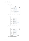
6.4.1 Define Inputs and Outputs
Before an input or output can be used in the configuration, it has to be defined with a
name and address.
IMS/IP inputs
1
The IMS/IP has two inputs that can be used by the Basic Alarm Manager. These inputs are
predefined in the Basic Alarm Manager at delivery. The states that can be detected are
open and close.
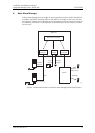
Alarm Module inputs
The number of inputs that can be used in the Basic Alarm Manager can be extended by
using an Alarm Module connected to the A-bus. The Alarm Module input is defined by a
name, the module address
2
on the A-bus, and the input number. The states that can be
detected are open and close.
1.The IMS/IP has two inputs. When the input is activated, it is called ‘close’ in the Basic Alarm Manager. For more
information about the inputs, see the ELISE Installation Guide.
2.Every module that is connected to the A-bus has a two digit hexadecimal address that is set with a DIP switch.