


TD 92322GB
2007-06-26/ Ver. D
Installation and Operation Manual
Integrated Message Server, IMS/IP-WiFi
4
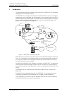
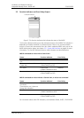
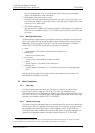
2.3 Function Indicator and Error Relay Output
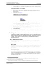
Figure 3. The function indicator that indicates the status of the IMS/IP
The function indicator and the error relay indicate the status of the IMS/IP. The indication is
dependent of whether the IMS/IP is connected to the A-bus or not, and also whether
there is a Central Unit connected to the A-bus. Which mode the IMS/IP uses is set on the
IMS/IP administration pages, see chapter 3.2.1 System 900 Interface on page 8 for more
information. The function indicator and error relay indications are described below.
IMS/IP connected to A-bus with a Central Unit
IMS/IP connected to A-bus without a Central Unit, or A-bus not connected
For information about other LED indications, see Installation Guide, ELISE2, TD 92232GB.
Status Function Indicator Error Relay
Communication with the Central
Unit.
Green Operates
No communication with the
Central Unit.
Flashing orange
(100ms ON/100 ms OFF)
Released
Shut down Flashing red
(1000ms ON/3000 ms OFF)
Released
Restart or reboot Flashing orange
(100ms ON/800 ms OFF)
Released
Status Function Indicator Error Relay
A-bus connection or no A-bus
connection.
(Connected or not, it does not
change the indication.)
Green Operates
Shut down Flashing red
(1000ms ON/3000 ms OFF)
Released
Restart or reboot Flashing orange
(100ms ON/800 ms OFF)
Released
Function indicator
003