


TD 92322GB
2007-06-26/ Ver. D
Installation and Operation Manual
Integrated Message Server, IMS/IP-WiFi
3
2 Installation (ELISE2)
This chapter is a complement to Installation Guide, ELISE2, TD 92232GB.
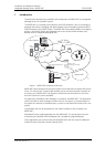
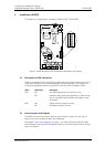
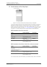
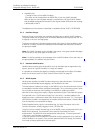
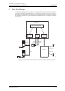
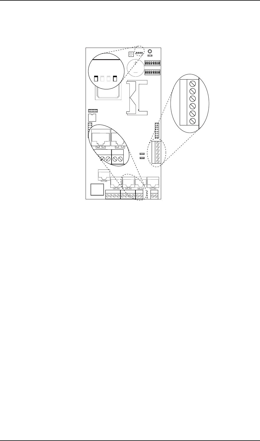
Figure 2. Board description with components described in this chapter.
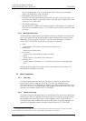
2.1 Description of LED Indications
There are a number of LEDs on ELISE that indicate the status of the software, see figure 2.
These status indications are software dependent and are described in this chapter. For
information regarding indications by other LEDs, see the ELISE2 Installation Guide.
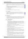
2.2 Internal Inputs and Outputs
The IMS/IP has two internal inputs and two open-collector outputs (J16, see figure 2
above), that can be used by the Basic Alarm Manager.
See chapter 6 Basic Alarm Manager on page 11, for more information about the Basic
Alarm Manager, and the ELISE2 Installation Guide for information about how to connect
inputs and outputs.
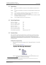
LED # LED status Indication
LED5 ON The IMS/IP applications are up and running.
OFF Problems when starting the applications, check the log
files on the IMS/IP Administration web page for more
information.
LED2 ON Paging waiting in queue to A-bus
OFF No paging in queue to A-bus
J2
J10
J16
J15
J4
J13J12
J11
J8
J7
J24
J14J6J5
J20
S3
LED6
LED7
S4
S5
S1
S2
IC24
J22
J9
IC1
BAT1
SW4
LED1
J1
SW2
SW3
1
LED2
LED3
LED4
LED5
1
8
1
8
16
2
21
1414 1
LED5
J16
5
1
6
J12
J11
J14J6
241
013
LED2