


20
Fourth Generation Versatile Interface Processor (VIP4) Installation and Configuration Guide
OL-3673-01
VIP4 Installation Procedures
Note To ensure compliance with EMI approvals by providing a tight EMI seal for the Cisco 7500 and the Cisco
7000 routers, we recommend that you first install interface processors in the interface processor slots
closest to the RSP slots, and then work out to the interface processor slots furthest from the RSP slots.
For more information on interface processor slots on your router, refer to the Cisco 7500 Series
Installation and Configuration Guide or the appropriate Quick Start Guide for the Cisco 7500 series
routers, or refer to Cisco 7000 Hardware Installation and Maintenance manual for the Cisco 7000 series
routers.
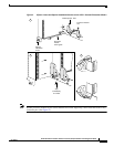
Figure 2 shows the functional details of inserting an interface processor and using the ejector levers.
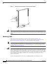
Figure 3 shows proper handling of an interface processor during installation.
Caution Remove or insert only one interface processor at a time. Allow the system to complete its discovery and
initialization of the interfaces before removing or inserting another interface processor. Disrupting the
sequence before the system has completed verification can cause the system to detect spurious hardware
failures.
Use the following procedure to install a new VIP4:
Step 1 Attach an ESD-preventive wrist strap between you and an unpainted chassis surface.
Step 2 Ensure that a console terminal is connected to the console port (on the RSP or RSP7000) and that your
console is turned on, or that you have a reliable Telnet connection to the system.
Step 3 Hold the VIP4 handle with one hand and place your other hand under the carrier to support the VIP4
and guide it into the slot. (See Figure 3.) Avoid touching the card or any connector pins.
Caution To prevent ESD damage, handle interface processors by the handles and carrier edges only.
Step 4 Place the back of the VIP4 in the slot and align the notch on the carrier with the groove in the slot. (See
Figure 2.)
Step 5 While keeping the VIP4 parallel to the backplane, carefully slide it into the slot until the back of the
faceplate makes contact with the ejector levers, and then stop. (See b in Figure 2.)
Caution Always use the ejector levers when installing or removing interface processors. An interface processor
that is partially seated in the backplane might cause the system to hang and subsequently crash, and
shoving or slamming the interface processor into the slot can damage the backplane pins and board.
Step 6 Using your thumbs, simultaneously push both ejector levers inward until the VIP4 is pushed entirely
into its slot. (See c in Figure 2.)
Step 7 Tighten both of the captive installation screws.
Caution To ensure proper EMI isolation for the router, be sure to tighten the captive installation screws on each
VIP4 immediately after you install it and before proceeding with the installation of each remaining VIP4
or other interface processor.