


23
Fourth Generation Versatile Interface Processor (VIP4) Installation and Configuration Guide
OL-3673-01
Checking the VIP4 Installation
Step 3 If the enabled LED on a port adapter fails to go on, suspect that the VIP4 board connector is not fully
seated in the backplane. Loosen the captive installation screws, and then firmly push both ejector levers
into place until they are approximately in the same orientation as the VIP4 faceplate. Tighten the
captive installation screws. After the system reinitializes the interfaces, the enabled LED on the port
adapter should go on. If it does, proceed to Step 5. If it does not, proceed to Step 4.
Step 4 If the enabled LED still fails to go on, remove the VIP4 and try installing it in another available
interface processor slot.
• If the enabled LED goes on when the VIP4 is installed in the new interface processor slot, suspect
a failed backplane port in the original interface processor slot.
• If the enabled LED still fails to go on, but other LEDs on the VIP4 port adapters go on to indicate
activity, proceed to Step 5 to resume the installation checkout; suspect that the enabled LED on the
port adapter has failed. Contact a service representative to report the problem and obtain further
instructions.
• If no LEDs on the VIP4 port adapters go on, suspect that the VIP4 is faulty. Contact a service
representative to report the problem and obtain further instructions.
• If just the enabled LED still fails to go on, remove the VIP4 and ensure the port adapter is firmly
installed in their port adapter slots. Remove and reinstall them accordingly.
Step 5 If the VIP4 is new and not a replacement, you have to configure the new interfaces. Proceed to the
appropriate configuration section in the configuration note that shipped with your port adapter. (This
does not have to be done immediately, but new interfaces are not be available until you configure them.)
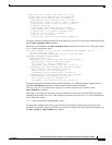
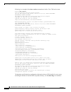
Step 6 If the VIP4 is a replacement, use the show interfaces type interface-processor-slot-
number/port-adapter-slot-number/interface-port-number command or the show controllers command
to verify the status of the interfaces. (See the following section, “Using show Commands to Verify the
VIP4 Status.”)
If you replaced a VIP4 with a new VIP4 with a greater number of interfaces (for example, if you replaced
a VIP4 with a single port adapter with a VIP4 with two port adapters), the system recognizes the
interfaces on the previously configured port adapter but does not recognize the additional port adapter
interfaces. The new interfaces remain in the shutdown state until you configure them.
Step 7 When the interfaces are up, check the activity of each interface by observing the status LEDs, which
are described in the appropriate LED section of your port adapter installation and configuration notes.
Step 8 In general, if an interface LED fails to go on and a cable is connected to the interface port, check the
cable connection and make certain it is properly seated in the connector.
If you experience other problems that you are unable to solve, contact a service representative for
assistance.
This completes the VIP4 installation. If you installed a new VIP4 or if you installed a replacement VIP4
with an additional port, you must now configure the new interface as described in the configuration note
that shipped with the port adapter or in the appropriate Cisco IOS software configuration documentation
listed in the section “Related Documentation” on page 2. The documentation is available on Cisco.com
and the Documentation CD-ROM.
Note Port adapter configuration information is beyond the scope of this document. Please refer to the specific
port adapter installation and configuration guide for more information.