


37
Fourth Generation Versatile Interface Processor (VIP4) Installation and Configuration Guide
OL-3673-01
VIP4 Maintenance Procedures
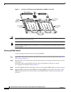
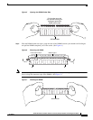
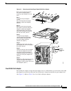
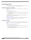
Figure 10 Removing and Installing a Single-Width Port Adapter
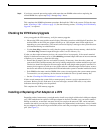
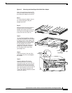
Dual-Width Port Adapter
Dual-width port adapters occupy both port adapter slots on a VIP4. Before you can install a dual-width
port adapter, you must first remove the slot divider that is located between the two port adapter slots.
(See Figure 11.) Refer to Table 5 for a list of dual-width port adapters.
EJECT
SLOT 0
SLOT 1
NORMAL
CPU HALT
RESET
AUX.
CONSOLE
ROUTE SWITCH PROCESSOR 2
SLAVE
MASTER
SLAVE/MASTER
I
O
DC FAIL
AC POWER
I
O
DC FAIL
AC POWER
A
B
Note: You must first remove the
VIP from the chassis before
removing a port adapter from the
VIP4.
Step 1
To remove the port adapter,
remove
the screw that secures the port
adapter (or blank port adapter).
(See A.)
Step 2
With the screw removed, grasp
the handle on the front of the port
adapter (or blank port adapter)
and carefully pull it out of its slot,
away from the edge connector at
the rear of the slot. (See A.)
29327
Screw
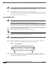
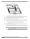
Step 3
To insert the port adapter,
carefully align the port adapter
carrier between the upper and
the lower edges of the port
adapter slot. (See B.)
Step 4
Install the screw in the rear of the
port adapter slot. Do not overtighten
the screw. (See A.)
Step 5
Carefully slide the new port adapter
into the port adapter slot until the
connector on the port adapter is
completely seated in the connector
at the rear of the port adapter slot.
(See B.)
Step 6
Reinstall the VIP motherboard in the
chassis, and tighten the captive
installation screw on each end of the
VIP faceplate. (See C.)
ENABLE
AL
EN
0
1
2
3
4
5
6
7
PA-MC-8TE1-SS7
C
Captive
installation
screw
Upper edge
Lower edge
Carrier